


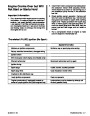
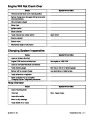


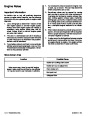
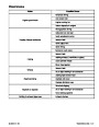


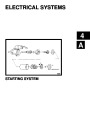


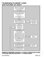

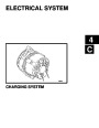


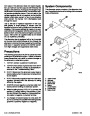
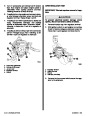


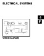


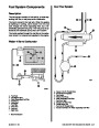
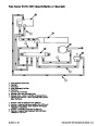
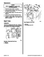
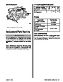
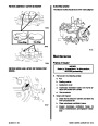


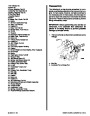


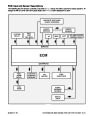


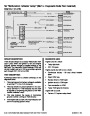


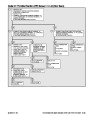
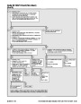
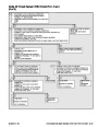


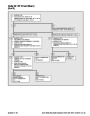


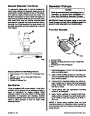


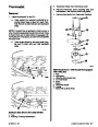


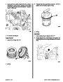


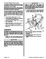
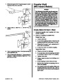


Spark Management
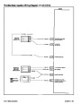
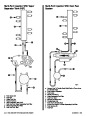
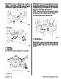
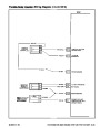
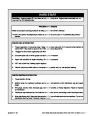
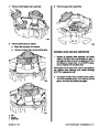
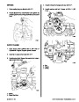
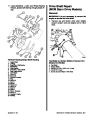
Distributor Module Mode
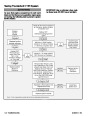
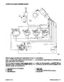
The following describes IC operation during cranking
and when the engine starts running. To help under-
stand how IC circuits operate, a relay with a double
set of contact points is shown in the IC module (refer
to the figures “Ignition Control Mode” and “ECM Con-
trolMode”).Solidstatecircuitryisusedinthemodule,
butshowingtherelaymakesiteasiertovisualizehow
the IC module functions.
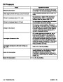
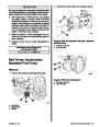
High Energy Ignition with Ignition
Control (IC)
The Electronic Fuel Injection is controlled by an En-
gine Control Module (ECM). This module is the
nerve/decision center of the system. It uses all the in-
formation itgatherstomanageignitionspark,deliver-
ing increased fuel economy and maximum engine
performance.
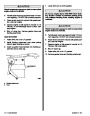
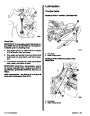
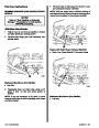
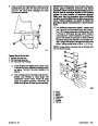
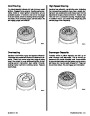
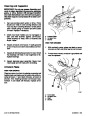
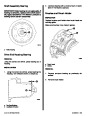
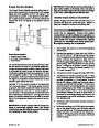
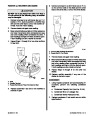
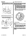
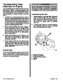
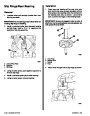
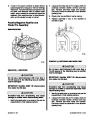
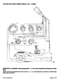
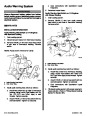
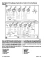
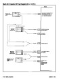
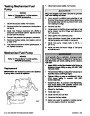
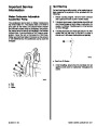
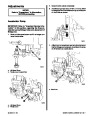
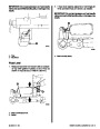
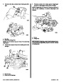
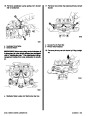
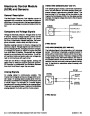
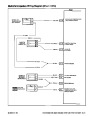
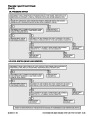
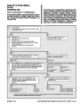
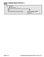
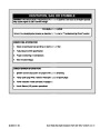
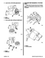
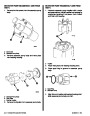
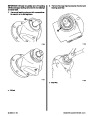
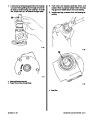
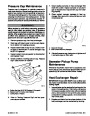
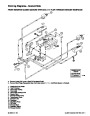
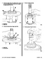
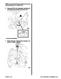
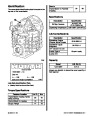
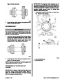
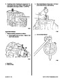
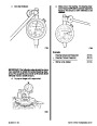
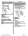
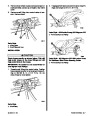
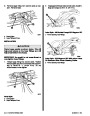
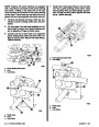
Duringcranking,therelayisinthede-energizedposi-
tion (see figure “Distributor Module Mode”). This con-
nects the pickup coil to the base of the transistor via
the signal converter. When the pickup coil applies a
positive voltage to the transistor, the transistor turns
ON. When voltage is removed, the transistor turns
OFF. When the transistor turns ON, current flows
through the primary winding of the ignition coil. When
it turns OFF, the primary current stops and a spark is
developed at the spark plug. A small amount of ad-
vance is built into the IC module via a timing circuit,
in case the engine remains in the ignition module tim-
ing mode.
The system uses inputs from sensors to make deci-
sions on the amount of spark advance or retard al-
lowed.
The system has been designed to control ignition ad-
vance and retard electronically by the ECM.
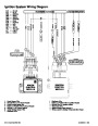
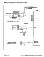
In order for the ECM to properly calculate spark ad-
vance, it must always know at what speed the engine
is running. The engine speed signal is accomplished
by a circuit within the distributor module which con-
verts the pickup coil voltage to a square wave refer-
ence signal that can be used by the ECM. This
square wave engine speed reference signal is known
as REF HI. The ECM must also have something to
compare the REF HI value against. Therefore, an
additional line is provided between the ECM and the
distributor module that is known as REF LO. These
two lines, between the ECM and the distributor, pro-
vide a precise indication of engine speed.
With the relay de-energized, a set of contacts (shown
closed) would ground the IC line signal.
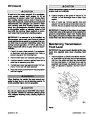
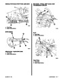
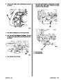
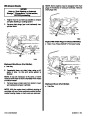
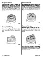
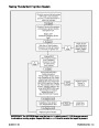
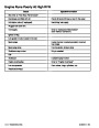
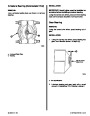
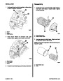
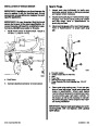
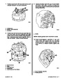
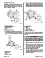
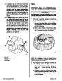
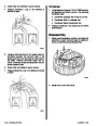
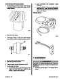
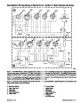
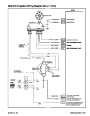
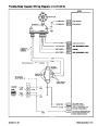
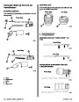
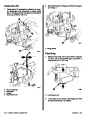
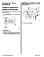
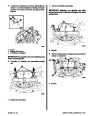
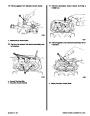
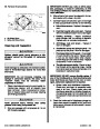
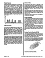
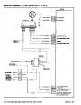
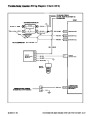
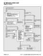
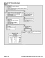
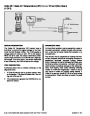
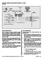
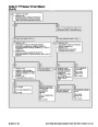
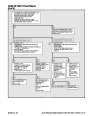
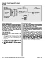
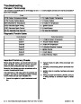
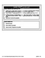
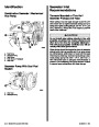
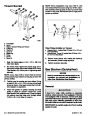
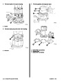
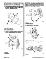
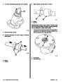
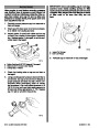
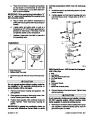
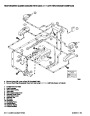
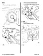
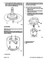
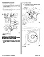
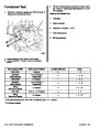
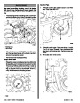
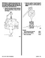
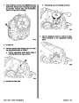
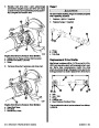
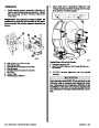
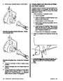
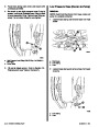
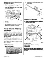
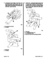
ECM Control Mode
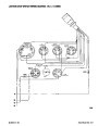
When the engine RPM reaches a predetermined val-
ue (for this example, 300 RPM), the ECM considers
the engine running and applies five volts on the by-
pass line to the IC module. This energizes the relay
and causes the contacts from the pickup coil as well
as the grounding contacts for the IC line to open (see
figure “ECM Control Mode”). This connects the IC
line to the base of the transistor, and bypasses the
ignition module timing control.
The two other lines between the ECM and distributor
which control the Ignition Control (IC) operation are
known as the bypass and IC circuits.
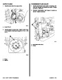
Modes Of Operation
There are two modes of ignition system operation:
The IC system is now controlled by the IC signal from
the ECM and the time at which the spark occurs can
be determined by a variable time circuit in the ECM.
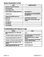
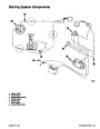
DISTRIBUTOR MODULE MODE
The ignition system operates independent of the
ECM. The distributor module module in the distribu-
tor maintains a base ignition timing and is able to ad-
vance timing to a total of 27 degrees. This mode is in
control when a Code 42 is detected while engine is
running and will have a noticeable affect on engine
operation.
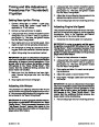
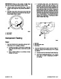
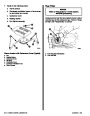
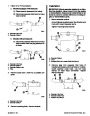
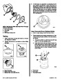
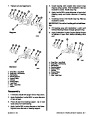
Base Ignition Timing
In order to check or change base timing on a HEI sys-
tem the ECM has to be entered into the service mode
by using a scan tool or code tool. The IC module will
go to base timing. The ECM will stabilize timing to al-
low timing adjustment. The ECM incorporates a
spark control override, which allows timing to be low-
ered if spark knock (detonation) is encountered dur-
ing normal operation. At this time, the timing can be
adjusted by turning the distributor.
ECM CONTROL MODE
The ECM control mode controls the ignition timing.
TheECMcalculatesthedesiredignitiontimingbased
on information it gets from its input sensors.
Index
5C-18 - ELECTRONIC FUEL INJECTION (MULTI-PORT AND THROTTLE BODY)
90-823224--2 796
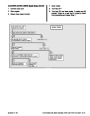
| Categories | Mercury MerCruiser Manuals |
|---|---|
| Tags | Mercury MerCruiser 454 CID, Mercury MerCruiser 502 CID |
| Model Year | 1993, 1994, 1995, 1996, 1997 |
| Download File |
|
| Document File Type | |
| Copyright | Attribution Non-commercial |
(4 votes, average: 4.5 out of 5)
Marine readers have rated 1993 1997 Mercury-MerCruiser GM V8 454 CID 7.4L and 502 CID 8.2L Marine Engines Service Manual Number 16 4.5 out of 5.0 based on 4 product reviews. Hugely helpful service manual! Perfect. Thank you!
Manuals are all Important for Technician
This book is invaluable if you do your own repairs. Great book.
Could not find a copy until a search brought me here.
Excellent print.
Thank you