


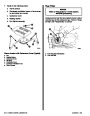


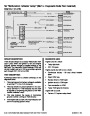


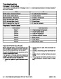


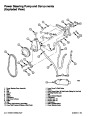


Diagnostic Information
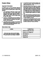
damaged. Always use jumper wires with the corre-
sponding mating terminals between connectors for
circuit checking. NEVER probe through connector
seals, wire insulation, secondary ignition wires,
boots, nipples or covers.
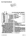
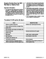
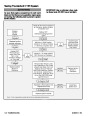
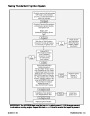
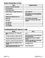
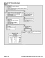
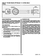
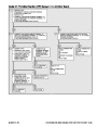
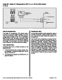
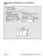
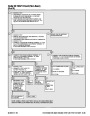
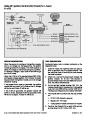
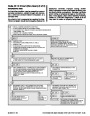
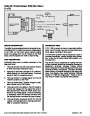
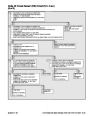
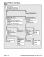
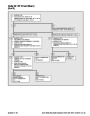
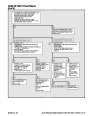
The diagnostic charts and functional checks in this
manual are designed to locate a faulty circuit or com-
ponent through logic based on the process of elimi-
nation. The charts are prepared with the require-
ment that the system functioned correctly at the
time of assembly and that there are no multiple
failures.
Microscopic damage or holes will result in eventual
water intrusion, corrosion and/or component or cir-
cuit failure.
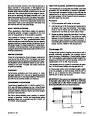
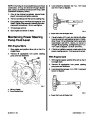
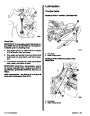
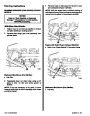
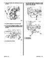
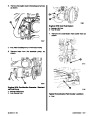
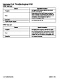
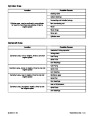
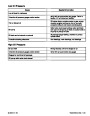
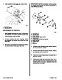
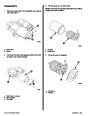
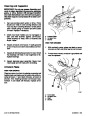
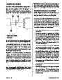
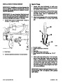
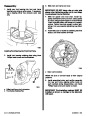
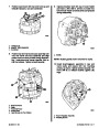
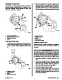
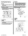
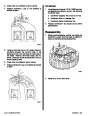
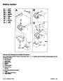
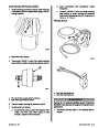
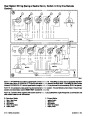
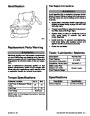
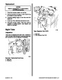
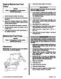
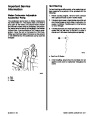
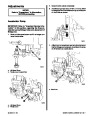
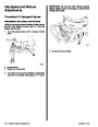
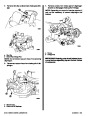
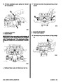
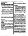
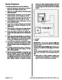
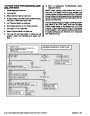
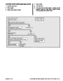
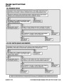
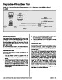
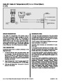
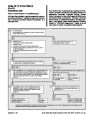
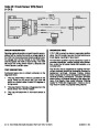
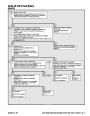
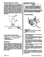
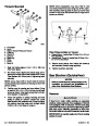
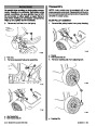
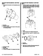
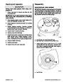
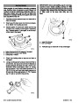
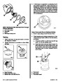
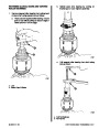
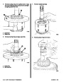
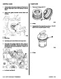
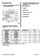
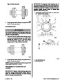
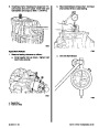
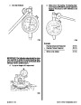
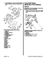
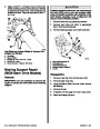
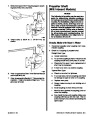
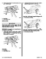
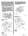
WIRE REPAIR
Wiring Harness Service
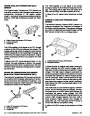
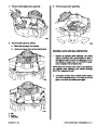
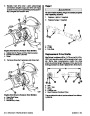
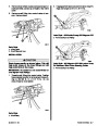
1.
2.
Locate damaged wire.
Marine engine control circuits contain many special
design features not found in standard land vehicle
wiring. Environmental protection is used extensively
to protect electrical contacts and proper splicing
methods must be used when necessary.
Remove insulation as required.
73048
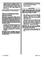
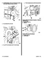
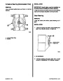
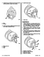
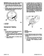
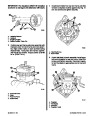
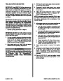
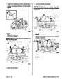
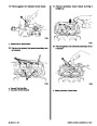
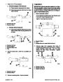
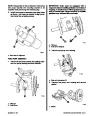
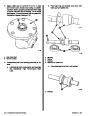
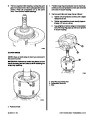
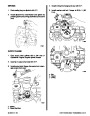
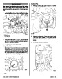
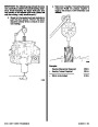
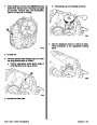
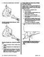
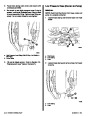
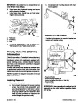
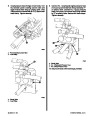
3.
4.
Splice two wires together using splice clips and
rosin core solder.
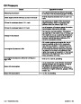
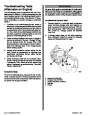
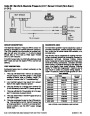
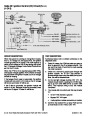
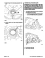
The proper operation of low amperage input/output
circuits depends upon good continuity between cir-
cuit connectors. It is important before component re-
placement and/or during normal troubleshooting pro-
cedures that a visual inspection of any questionable
mating connector is performed. Mating surfaces
should be properly formed, clean and likely to make
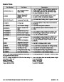
proper contact. Some typical causes of connector
problems are listed below.
73048
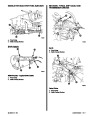
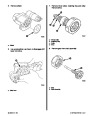
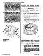
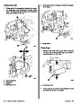
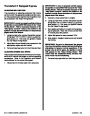
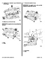
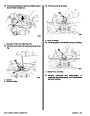
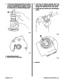
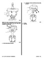
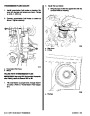
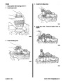
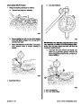
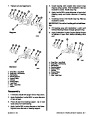
Cover splice with heat shrink sleeve to insulate
from other wires.
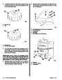
1.
2.
3.
4.
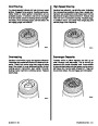
Improperly formed contacts and/or connector
housing.
73048
Damaged contacts or housing due to improper
engagement.
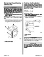
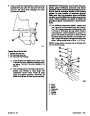
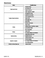
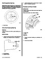
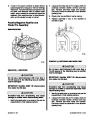
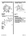
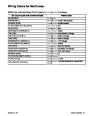
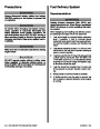
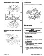
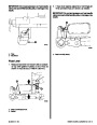
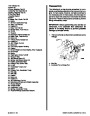
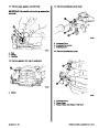
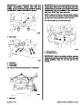
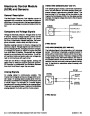
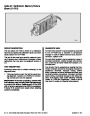
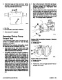
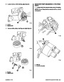
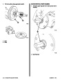
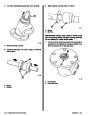
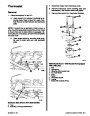
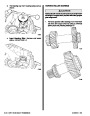
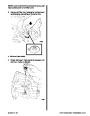
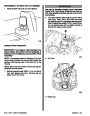
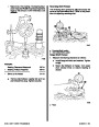
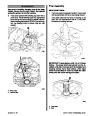
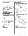
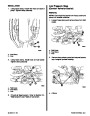
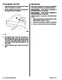
Wiring Connector Service
Corrosion, sealer or other contaminants on the
contact mating surfaces.
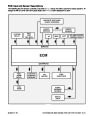
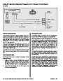
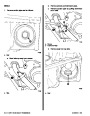
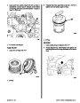
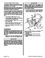
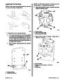
Most connectors in the engine compartment are pro-
tected against moisture and dirt which could create
oxidation and deposits on the terminals. This protec-
tion is important because of the very low voltage and
current levels found in the electronic system. The
connectors have a lock which secures the male and
female terminals together. A secondary lock holds
the seal and terminal into the connector.
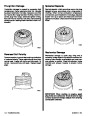
Incomplete mating of the connector halves dur-
ing initial assembly or during subsequent trouble-
shooting procedures.
5.
Tendency for connectors to come apart due to
vibration and/or temperature cycling.
6.
7.
Terminals not fully seated in the connector body.
Inadequate terminal crimps to the wire.
When diagnosing, open circuits are often difficult to
locate by sight because oxidation or terminal mis-
alignment are hidden by the connectors. Merely wig-
gling a connector on a sensor or in the wiring harness
may locate the open circuit condition. This should al-
ways be considered when an open circuit or failed
sensor is indicated. Intermittent problems may also
be caused by oxidized or loose connections.
Wire harnesses should be replaced with proper part
number harnesses. When signal wires are spliced
into a harness, use the same gauge wire with high
temperature insulation only.
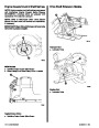
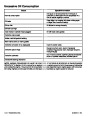
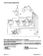
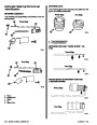
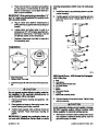
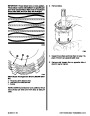
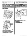
With the low current and voltage levels found in the
system, it is important that the best possible bond be
made at all wire splices by soldering the splices, as
shown in the following illustrations. Use care when
probing a connector or replacing connector termi-
nals. It is possible to short between opposite termi-
nals. If this happens, certain components can be
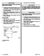
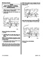
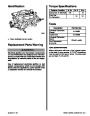
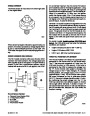
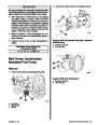
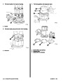
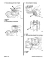
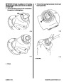
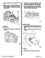
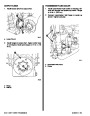
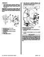
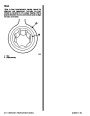
Before making a connector repair, be certain of the
type of connector. Some connectors look similar but
are serviced differently. Replacement connectors
and terminals are listed in the Parts Catalog.
Ensure that the connector seals are not deformed or
crushed when mating the connectors together.
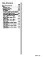
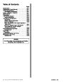
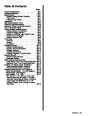
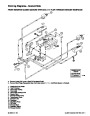
Index
5C-2 - ELECTRONIC FUEL INJECTION (MULTI-PORT AND THROTTLE BODY)
90-823224--2 796
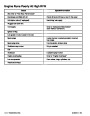
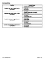
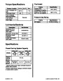
| Categories | Mercury MerCruiser Manuals |
|---|---|
| Tags | Mercury MerCruiser 454 CID, Mercury MerCruiser 502 CID |
| Model Year | 1993, 1994, 1995, 1996, 1997 |
| Download File |
|
| Document File Type | |
| Copyright | Attribution Non-commercial |
(4 votes, average: 4.5 out of 5)
Marine readers have rated 1993 1997 Mercury-MerCruiser GM V8 454 CID 7.4L and 502 CID 8.2L Marine Engines Service Manual Number 16 4.5 out of 5.0 based on 4 product reviews. Hugely helpful service manual! Perfect. Thank you!
Manuals are all Important for Technician
This book is invaluable if you do your own repairs. Great book.
Could not find a copy until a search brought me here.
Excellent print.
Thank you