


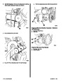


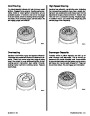
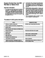


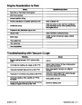


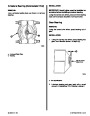


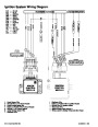
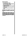


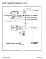

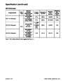


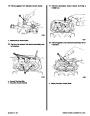


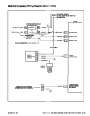


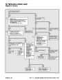


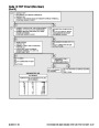
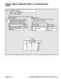
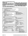


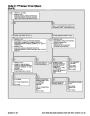
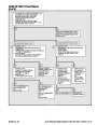
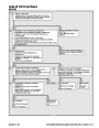
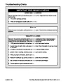


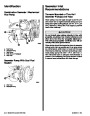
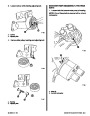
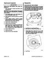


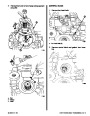
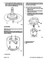


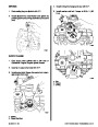


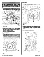
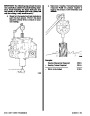
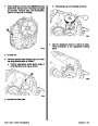


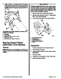
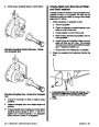


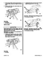


Knock Control Module
IMPORTANT: If there is abnormal mechanical en-
gine noise (rattles or knocks), they may give a
falseknockretardsignal.Iffueloctaneistoohigh
or too low, a false signal can also be sent.
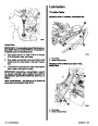
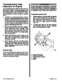
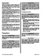
The Knock Control Module contains solid state cir-
cuitry which monitors the knock sensor’s AC voltage
signal and then supplies an 8-10 volt signal, if no
spark knock is present, to the Ignition Control Mod-
ule. If spark knock is present, the Knock module will
remove the 8-10 volt signal to the Ignition Control
Module.
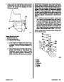
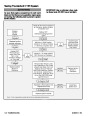
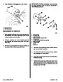
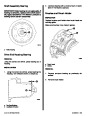
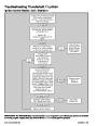
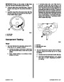
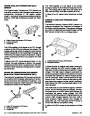
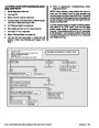
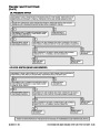
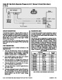
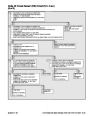
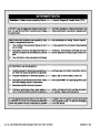
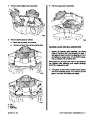
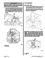
TESTING KNOCK MODULE AND SENSOR
NOTE: A digital volt-ohmmeter (DVOM) and an un-
powered test light (low power test light - 300mA or
less) are needed to conduct the following test.
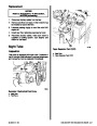
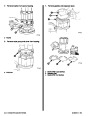
a
b
!
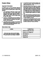
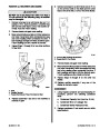
WARNING
Avoid fire or explosion. Ensure that engine
compartment is well ventilated and gasoline va-
pors are not present when performing electrical
tests inside the engine compartment. Sparks
generated by electrical tests could ignite gaso-
line vapors causing fire or explosion.
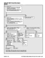
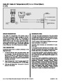
1.
2.
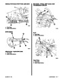
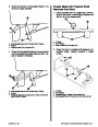
Start engine and warm it up to normal operating
temperature.
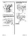
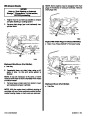
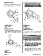
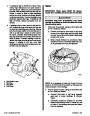
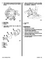
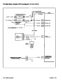
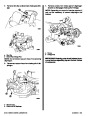
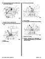
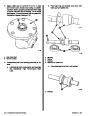
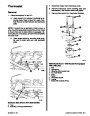
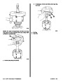
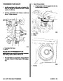
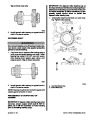
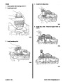
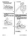
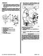
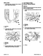
c
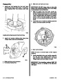
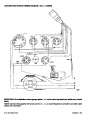
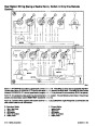
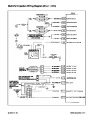
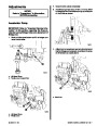
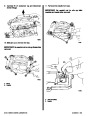
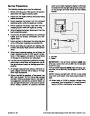
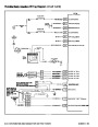
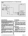
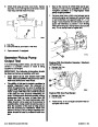
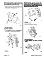
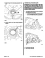
Connect the positive (+) lead from the DVOM to
the PURPLE/WHITE timing terminal that comes
fromtheengineharness(seepreviouswiringdia-
gram). Connect the negative (–) lead from the
DVOM to a good engine ground (–). With the en-
gine running, there should be 8-10 volts on this
circuit. If voltage is not present, check to ensure
that there is 12 volts to the knock module (PUR-
PLE wire Terminal “B”).
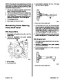
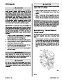
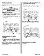
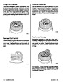
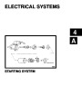
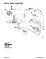
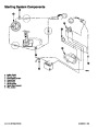
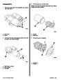
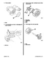
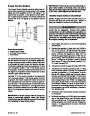
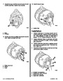
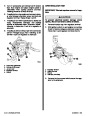
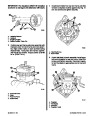
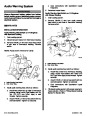
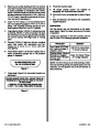
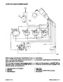
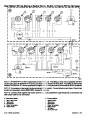
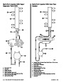
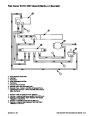
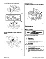
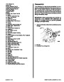
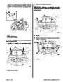
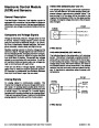
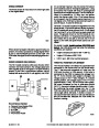
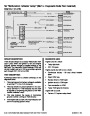
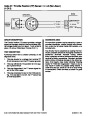
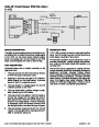
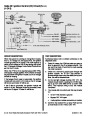
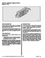
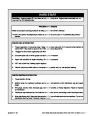
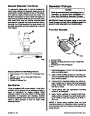
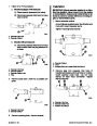
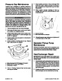
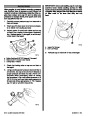
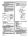
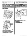
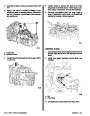
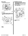
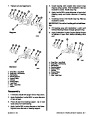
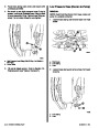
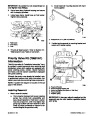
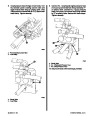
Knock Sensor System
a - Positive Lead (12 Volts)
b - 8-10 Volts To Knock Sensor
c - Knock Sensor
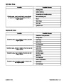
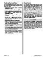
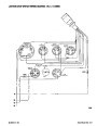
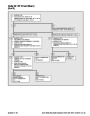
It is extremely important that the correct knock mod-
ule and sensor be used for the engine application.
Using an incorrect knock module or sensor will result
in unrecognized spark knock and engine damage.
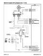
The Knock module terminal B is powered by 12 volts
from the ignition switch. If the 12 volt power source
isnotpresent,theknockmodulecannotsendan8-10
volt signal to the ignition control module and a false
constant spark retard will result.
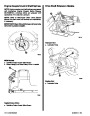
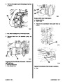
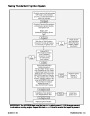
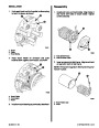
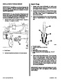
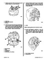
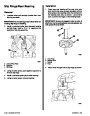
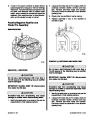
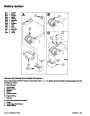
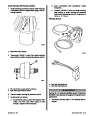
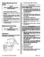
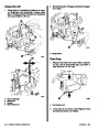
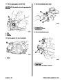
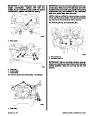
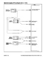
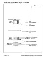
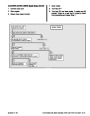
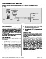
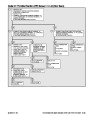
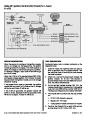
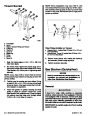
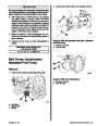
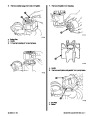
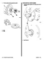
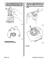
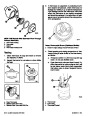
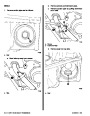
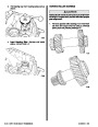
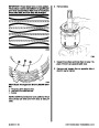
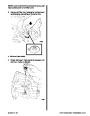
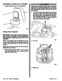
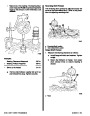
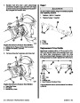
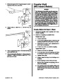
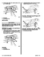
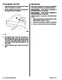
3. Advance the throttle to approximately 1500RPM.
4.
Disconnect the harness connector (BLUE wire)
from the knock sensor. Connect the unpowered
test light to a positive (+) 12 volt source. To simu-
late an AC voltage, rapidly tap the knock sensor
harness terminal with the test light. If knock mod-
ule and wiring is functioning properly, you should
seeavoltagedropontheDVOM.Ifavoltagedrop
is not seen, check the BLUE wire from the sensor
to the knock module for a short or open circuit. If
the circuit is functioning properly to this point, the
knock sensor may not be functioning. Proceed to
the following step.
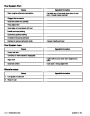
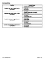
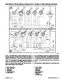
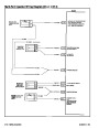
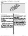
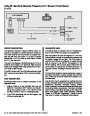
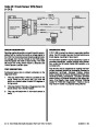
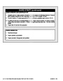
Terminal “E” of the knock module is the signal line
from the knock sensor. If this circuit opens or shorts
to ground, the knock module will never remove the
8-10
volt signal from terminal “C” to and no spark re-
tard will occur. The ground circuit for the knock mod-
ule is connected to terminal “D”. If the ground circuit
opens, the knock module will not be able to remove
the 8-10 volt signal and spark knock cannot be con-
trolled.
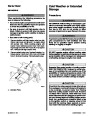
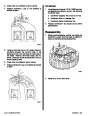
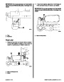
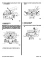
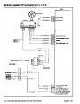
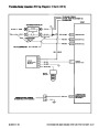
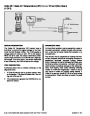
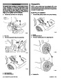
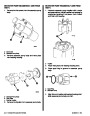
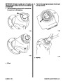
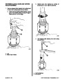
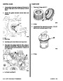
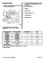
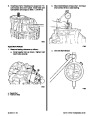
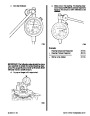
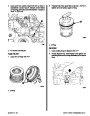
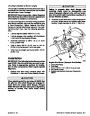
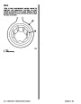
5.
6.
Reconnect the knock sensor harness connector
to the sensor.
IMPORTANT: If knock sensor wire is routed too
close to secondary ignition wires, the Knock
module may see the interference as a knock sig-
nal, resulting in false timing retard.
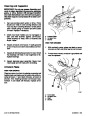
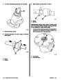
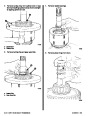
While still watching the DVOM, lightly and rapidly
tap on the engine block near the knock sensor
with a small hammer. If the knock sensor is func-
tioning properly, you should see the voltage de-
crease. If a voltage drop is not seen, the knock
sensor is faulty.
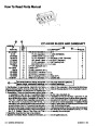
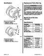
Index
90-823224--2 796
IGNITION SYSTEM - 4B-21
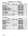
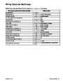
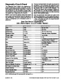
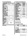
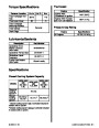
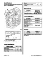
| Categories | Mercury MerCruiser Manuals |
|---|---|
| Tags | Mercury MerCruiser 454 CID, Mercury MerCruiser 502 CID |
| Model Year | 1993, 1994, 1995, 1996, 1997 |
| Download File |
|
| Document File Type | |
| Copyright | Attribution Non-commercial |
(4 votes, average: 4.5 out of 5)
Marine readers have rated 1993 1997 Mercury-MerCruiser GM V8 454 CID 7.4L and 502 CID 8.2L Marine Engines Service Manual Number 16 4.5 out of 5.0 based on 4 product reviews. Hugely helpful service manual! Perfect. Thank you!
Manuals are all Important for Technician
This book is invaluable if you do your own repairs. Great book.
Could not find a copy until a search brought me here.
Excellent print.
Thank you