


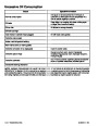


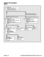


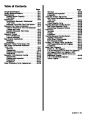


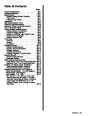


Table of Contents
Page
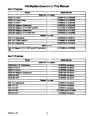
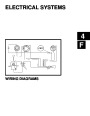
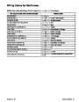
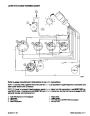
Wiring Harness Diagrams . . . . . . . . . . . . . . . 5C-36
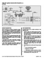
MCM 7.4LX / MIE 7.4L Throttle Body Injection
Bluewater Inboard . . . . . . . . . . . . . . . . . . . . 5C-36
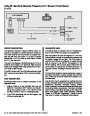
MCM 7.4LX Multi-Port Injection / 454 / 502
Magnum Multi-Port Injection / MIE 454
Page
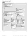
General Information . . . . . . . . . . . . . . . . . . . . . 5C-1
Introduction . . . . . . . . . . . . . . . . . . . . . . . . . . . 5C-1
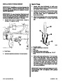
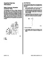
Visual/Physical Inspection . . . . . . . . . . . . . . 5C-1
Basic Knowledge and Tools Required . . . . 5C-1
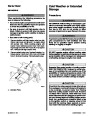
Electrostatic Discharge Damage . . . . . . . . . 5C-1
Diagnostic Information . . . . . . . . . . . . . . . . . 5C-2
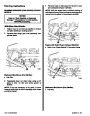
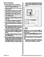
Wiring Harness Service . . . . . . . . . . . . . . . . 5C-2
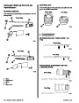
Wiring Connector Service . . . . . . . . . . . . . . . 5C-2
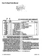
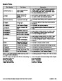
Abbreviations . . . . . . . . . . . . . . . . . . . . . . . . . . . . 5C-3
Changes In Terminology . . . . . . . . . . . . . . . . 5C-4
Diagnostic Trouble Codes . . . . . . . . . . . . . . 5C-4
ECM Self-Diagnostics . . . . . . . . . . . . . . . . . . . . . 5C-5
Diagnostic Code Tool With Malfunction
Indicator Lamp . . . . . . . . . . . . . . . . . . . . . . . . 5C-5
Intermittent Malfunction Indicator Lamp . . . 5C-5
Reading Codes . . . . . . . . . . . . . . . . . . . . . . . . 5C-5
Scan Tools . . . . . . . . . . . . . . . . . . . . . . . . . . . 5C-6
EFI Diagnostic Circuit Check . . . . . . . . . . . . 5C-6
Scan Tool Use with Intermittents . . . . . . . . . 5C-6
Non-Scan Diagnosis of Driveability Concerns
(With No Codes Set) . . . . . . . . . . . . . . . . . . . 5C-7
Special Tools . . . . . . . . . . . . . . . . . . . . . . . . . . 5C-8
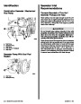
Service Precautions . . . . . . . . . . . . . . . . . . . . 5C-9
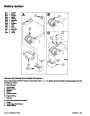
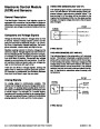
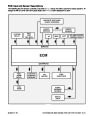
Electronic Control Module (ECM)
Tournament Ski Multi-Port Injection /
502
Magnum Multi-Port Injection . . . . . . . 5C-38
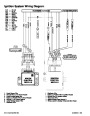
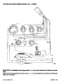
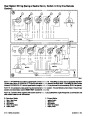
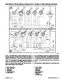
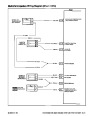
Multi-Port Injection Wiring Diagram
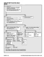
(Chart 1 Of 4) . . . . . . . . . . . . . . . . . . . . . . . . 5C-40
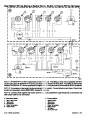
Multi-Port Injection Wiring Diagram
(Chart 2 Of 4) . . . . . . . . . . . . . . . . . . . . . . . . 5C-41
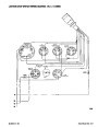
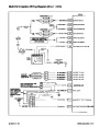
Multi-Port Injection Wiring Diagram
(Chart 3 Of 4) . . . . . . . . . . . . . . . . . . . . . . . . 5C-42
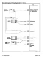
Multi-Port Injection Wiring Diagram
(Chart 4 Of 4) . . . . . . . . . . . . . . . . . . . . . . . . 5C-43
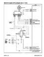
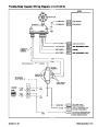
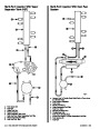
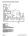
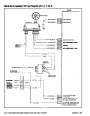
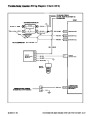
Throttle Body Injection Wiring Diagram
(Chart 1 of 4) . . . . . . . . . . . . . . . . . . . . . . . . 5C-44
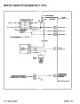
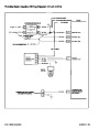
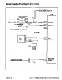
Throttle Body Injection Wiring Diagram
(Chart 2 Of 4) . . . . . . . . . . . . . . . . . . . . . . . . 5C-45
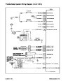
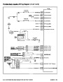
Throttle Body Injection Wiring Diagram
(Chart 3 Of 4) . . . . . . . . . . . . . . . . . . . . . . . . 5C-46
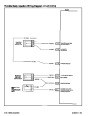
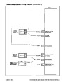
Throttle Body Injection Wiring Diagram
(Chart 4 Of 4) . . . . . . . . . . . . . . . . . . . . . . . . 5C-47
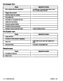
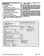
Diagnostic Circuit Check . . . . . . . . . . . . . . . 5C-49
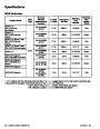
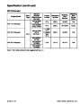
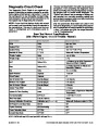
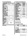
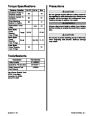
Scan Tool Normal Specifications
(Idle /Warm Engine/Closed
Throttle/Neutral) . . . . . . . . . . . . . . . . . . . . 5C-49
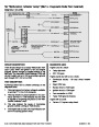
No “Malfunction Indicator Lamp” (Marine
Diagnostic Code Tool Installed) . . . . . . . . 5C-52
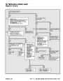
No DLC Data or Will Not Flash Code 12
“Malfunction Indicator Lamp” On Steady
(Marine Diagnostic Code Tool Installed)
Chart A-2 (1 of 2) . . . . . . . . . . . . . . . . . . . . . 5C-54
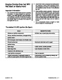
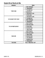
Engine Cranks but Will Not Run
Chart A-3 (1 of 4) . . . . . . . . . . . . . . . . . . . . 5C-56
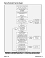
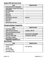
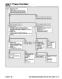
Multi-Port Injection Fuel System Diagnosis
Chart A-7 (1 of 6) . . . . . . . . . . . . . . . . . . . . . 5C-60
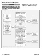
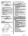
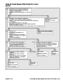
Throttle Body Injection Fuel System
Diagnosis Chart A-7 (1 of 6) . . . . . . . . . . . 5C-66
EFI System/Ignition Relay Check
and Sensors . . . . . . . . . . . . . . . . . . . . . . . . . . 5C-10
General Description . . . . . . . . . . . . . . . . . . . 5C-10
Computers and Voltage Signals . . . . . . . . 5C-10
Analog Signals . . . . . . . . . . . . . . . . . . . . . . . 5C-10
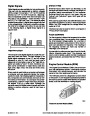
Digital Signals . . . . . . . . . . . . . . . . . . . . . . . . 5C-11
Engine Control Module (ECM) . . . . . . . . . . 5C-11
Speed Density System . . . . . . . . . . . . . . . . 5C-12
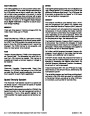
ECM Input and Sensor Descriptions . . . . . 5C-13
Spark Management . . . . . . . . . . . . . . . . . . . . . 5C-18
High Energy Ignition with Ignition
Control (IC) . . . . . . . . . . . . . . . . . . . . . . . . . 5C-18
Modes Of Operation . . . . . . . . . . . . . . . . . . 5C-18
Distributor Module Mode . . . . . . . . . . . . . . . 5C-18
ECM Control Mode . . . . . . . . . . . . . . . . . . . 5C-18
Base Ignition Timing . . . . . . . . . . . . . . . . . . 5C-18
Results of Incorrect Operation . . . . . . . . . . 5C-20
Fuel Metering System . . . . . . . . . . . . . . . . . . 5C-20
General Description . . . . . . . . . . . . . . . . . . . 5C-20
Modes of Operation . . . . . . . . . . . . . . . . . . . 5C-20
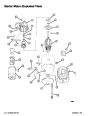
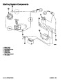
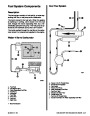
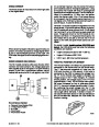
Fuel Metering System Components . . . . . 5C-22
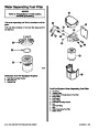
Multi-Port Vapor Separator Tank (VST) . . 5C-22
Cool Fuel System . . . . . . . . . . . . . . . . . . . . . 5C-23
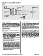
Throttle Body Injection Components . . . . . 5C-24
Multi-Port Injection Components . . . . . . . . 5C-26
Throttle Body Assembly . . . . . . . . . . . . . . . 5C-27
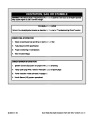
ECM Connector and Symptom Charts . . . 5C-29
ECM Connector and EFI Symptoms Chart
(1
of 2) . . . . . . . . . . . . . . . . . . . . . . . . . . . . . . 5C-72
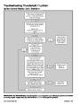
Ignition System Check (1 of 2) . . . . . . . . . . 5C-74
Ignition System Check (2 of 2) . . . . . . . . . . 5C-76
Idle Air Control (IAC) Functional Test
(1
of 2) . . . . . . . . . . . . . . . . . . . . . . . . . . . . . . 5C-78
Lanyard Stop Circuit Check (Emergency Stop)
Circuit Check (1 of 2) . . . . . . . . . . . . . . . . . . 5C-80
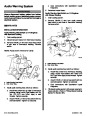
Audio Warning Buzzer Circuit Check
(1
of 2) . . . . . . . . . . . . . . . . . . . . . . . . . . . . . . 5C-82
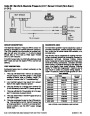
Discrete Input Circuit Check
(Power Reduction Mode) (Non-Scan)
(1
of 2) . . . . . . . . . . . . . . . . . . . . . . . . . . .
5C-84
Diagnostics-Without Scan Tool . . . . . . . . . . 5C-86
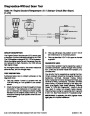
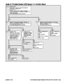
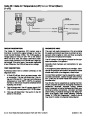
Code 14: Engine Coolant Temperature (ECT)
Sensor Circuit (Non-Scan) (1 of 2) . . . . . . 5C-86
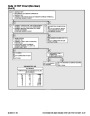
Code 21: Throttle Position (TP) Sensor Circuit
(Non-Scan) (1 Of 2) . . . . . . . . . . . . . . . . . . . 5C-88
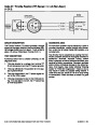
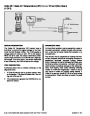
Code 23: Intake Air Temperature (IAT) Sensor
Circuit (Non-Scan)
(J-1 Circuits) . . . . . . . . . . . . . . . . . . . . . . . . . . . 5C-30
ECM Connector and EFI Symptoms Chart
(J-2 Circuits) . . . . . . . . . . . . . . . . . . . . . . . . . . . 5C-33
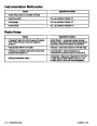
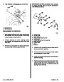
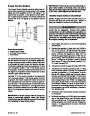
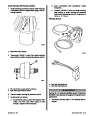
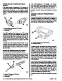
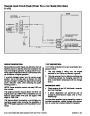
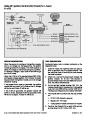
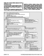
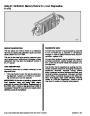
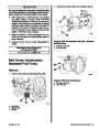
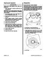
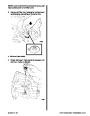
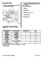
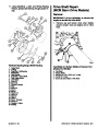
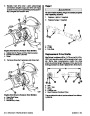
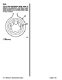
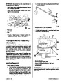
Multi Port Injector Balance Test . . . . . . . . . 5C-34
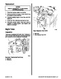
Fuel Injector Balance Test Set-up
(Multi-Port Injection) . . . . . . . . . . . . . . . . . . 5C-35
(1
Of 2) . . . . . . . . . . . . . . . . . . . . . . . . . . . . . . 5C-90
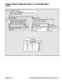
Code 33: Manifold Absolute Pressure (MAP)
Sensor Circuit (Non-Scan) (1 Of 2) . . . . . . 5C-92
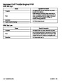
Code 42: Ignition Control (IC) Circuit
(Non-Scan) (1 of 2) . . . . . . . . . . . . . . . . . . . 5C-94
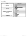
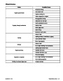
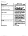
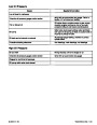
Index
5C-–2 - ELECTRONIC FUEL INJECTION (MULTI-PORT AND THROTTLE BODY)
90-823224--2 796
| Categories | Mercury MerCruiser Manuals |
|---|---|
| Tags | Mercury MerCruiser 454 CID, Mercury MerCruiser 502 CID |
| Model Year | 1993, 1994, 1995, 1996, 1997 |
| Download File |
|
| Document File Type | |
| Copyright | Attribution Non-commercial |
(4 votes, average: 4.5 out of 5)
Marine readers have rated 1993 1997 Mercury-MerCruiser GM V8 454 CID 7.4L and 502 CID 8.2L Marine Engines Service Manual Number 16 4.5 out of 5.0 based on 4 product reviews. Hugely helpful service manual! Perfect. Thank you!
Manuals are all Important for Technician
This book is invaluable if you do your own repairs. Great book.
Could not find a copy until a search brought me here.
Excellent print.
Thank you