


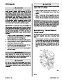


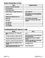


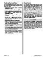


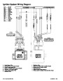


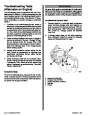


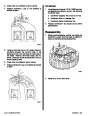
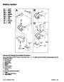


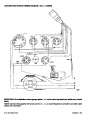
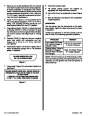


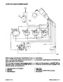
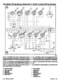
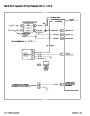
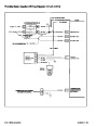

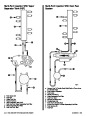
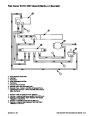


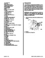
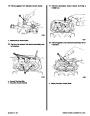


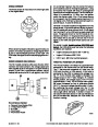


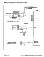

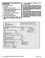
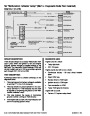


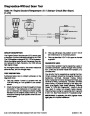
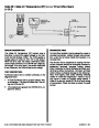
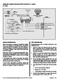
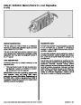


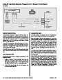
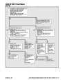
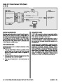
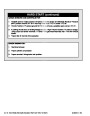


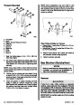
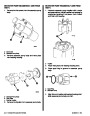


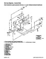


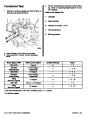


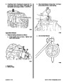


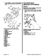
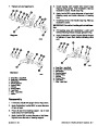
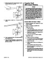


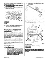
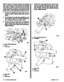


Circuit Description
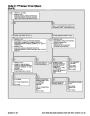
Knock Control Module
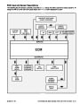
D The knock control module receives it’s power (+)
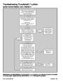
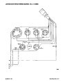
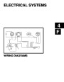
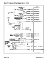
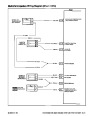
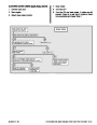
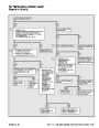
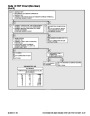
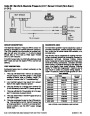
Refer to the circuit wiring diagram on the following
page for reference to this circuit description.
from the PURPLE wire “4”.
D Knock module ground (–) is accomplished thru
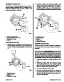
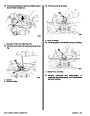
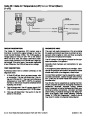
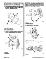
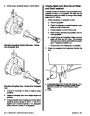
Ignition Control Module
the BLACK wire “2”.
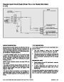
D The ignition module receives its power (+) thru
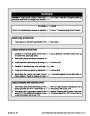
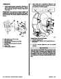
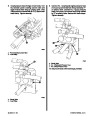
D The PURPLE/WHITE wire “3” carries the signal
from the knock control module to the ignition
control module.
the PURPLE wire “9”.
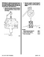
D Ignition module ground (–) is accomplished thru
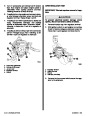
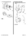
D The BLUE wire “1” carries the signal from the
the BLACK wire “10”.
D There is also a Case Ground (–) wire “12” that is
connected to one of the ignition module attaching
screws.
knock sensor to the knock module.
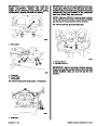
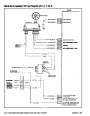
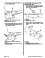
D The 12 volt signal from the ignition module to the
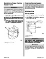
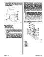
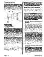
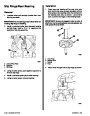
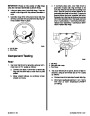
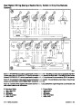
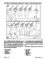
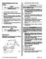
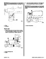
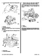
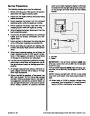
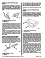
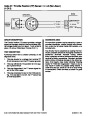
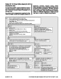
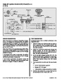
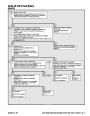
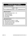
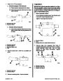
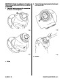
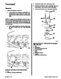
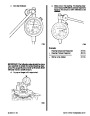
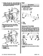
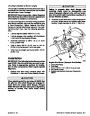
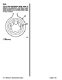
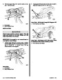
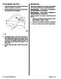
Ignition Control System Timing Lead
distributor is carried thru the WHITE/RED wire
The ignition control system has a lead with bullet con-
nector “11” that is connected into the PURPLE/
WHITE wire “3”. This lead is used for performing the
following tests and procedures:
“8”,
to the distributor sensor and back to the
ignition module thru the WHITE/GREEN wire “7”.
D The tachometer signal is carried to the
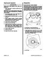
D Setting “Base Ignition Timing”
instrument panel thru the GRAY wire “11”.
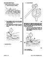
D The PURPLE/WHITE wire “3” carries the signal
from the knock control module to the ignition
control module.
D
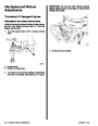
Setting “Engine Idle Speed”
D Setting “Idle Mixture”
D
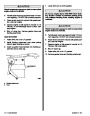
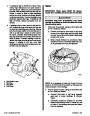
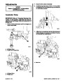
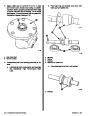
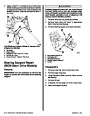
Testing Knock Control Circuit
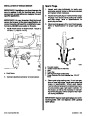
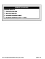
D There are two BLACK wires “5” that have bullet
connectors. This circuit is reserved for future
options. On current models, the two BLACK
wires must be connected for the system to
function properly.
This lead, when connected to an engine ground (–),
locks the ignition control module into the “Base Tim-
ing” mode.
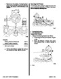
D The TAN/BLU wire “6” carries a signal from the
Audio Warning circuit to the ignition module.
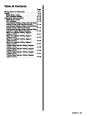
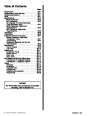
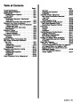
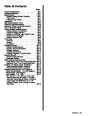
Index
90-823224--2 796
IGNITION SYSTEM - 4B-17
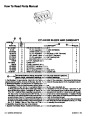
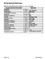
| Categories | Mercury MerCruiser Manuals |
|---|---|
| Tags | Mercury MerCruiser 454 CID, Mercury MerCruiser 502 CID |
| Model Year | 1993, 1994, 1995, 1996, 1997 |
| Download File |
|
| Document File Type | |
| Copyright | Attribution Non-commercial |
(4 votes, average: 4.5 out of 5)
Marine readers have rated 1993 1997 Mercury-MerCruiser GM V8 454 CID 7.4L and 502 CID 8.2L Marine Engines Service Manual Number 16 4.5 out of 5.0 based on 4 product reviews. Hugely helpful service manual! Perfect. Thank you!
Manuals are all Important for Technician
This book is invaluable if you do your own repairs. Great book.
Could not find a copy until a search brought me here.
Excellent print.
Thank you