


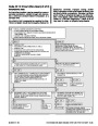


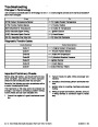


If a scan tool is used to read the codes, follow the
manufacturer’s instructions.
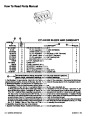
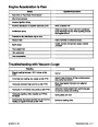
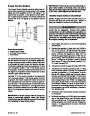
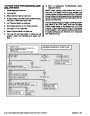
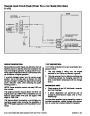
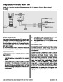
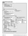
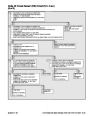
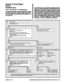
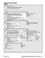
EFI Diagnostic Circuit Check
After the visual/physical inspection, the EFI Diagnos-
tic Circuit Check is the starting point for all diagnostic
procedures. Refer to EFI Diagnostic Circuit Check.
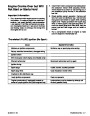
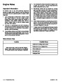
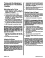
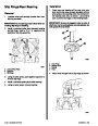
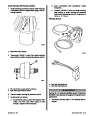
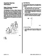
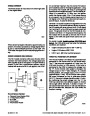
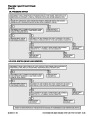
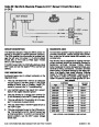
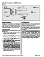
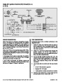
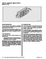
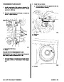
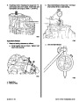
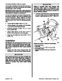
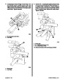
SERVICE MODE
When the diagnostic code tool is installed at the Data
Link Connector (DLC) and the selector switch is set
at SERVICE, the system will enter what is called the
SERVICE mode. In this mode the ECM will:
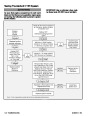
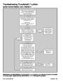
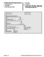
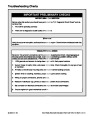
Thecorrectproceduretodiagnoseaproblemistofol-
low two basic steps.
1.
Are the on-board diagnostics working? This is
determined by performing the EFI Diagnostic Cir-
cuit Check. Since this is the starting point for the
diagnostic procedures, always begin here. If the
on-board diagnostics are not working, the EFI
Diagnostic Circuit Check will lead to a diagnostic
chart in “Diagnostics” to correct the problem. If
the on-board diagnostics are working correctly,
go to step 2.
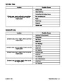
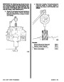
1.
Display a Code 12 by flashing the Malfunction In-
dicator Lamp (indicating the system is operating
correctly).
2.
Display any stored codes by flashing the Mal-
function Indicator Lamp. Each code will be
flashed three times, then Code 12 will be flashed
again.
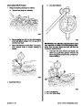
3.
4.
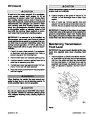
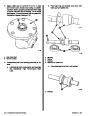
The IAC valve moves to its fully extended posi-
tion, blocking the idle air passage. This is impor-
tant to remember, as an attempt to run the vessel
while in SERVICE mode will most likely result in
an abnormally low idle speed or a stalled engine.
2.
If there is a code stored: If a code is stored, go di-
rectly to the numbered code chart in “Diagnos-
tics.” This will determine if the fault is still present.
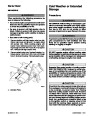
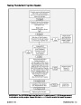
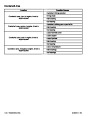
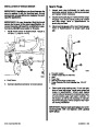
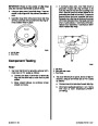
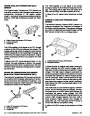
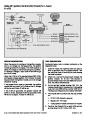
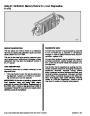
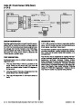
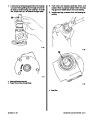
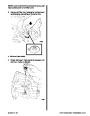
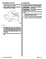
Scan Tool Use with Intermittents
Holds ignition advance steady.
The scan tool allows manipulation of wiring har-
nesses or components with the engine not running,
while observing the scan tool readout.
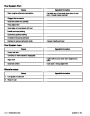
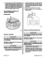
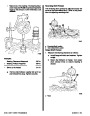
NORMAL MODE
Engines can be monitored in the normal mode. Cer-
tain parameters can be observed without changing
the engine operating characteristics.
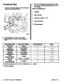
The scan tool can be plugged in and observed while
running the vessel under the condition when the Mal-
function Indicator Lamp turns ON momentarily or
when the engine driveability is momentarily poor. If
the problem seems to be related to certain parame-
tersthatcanbecheckedonthescantool,theyshould
be checked while running the vessel. If there does
not seem to be any correlation between the problem
and any specific circuit, the scan tool can be checked
on each position, watching for a period of time to see
if there is any change in the readings that indicates
intermittent operation.
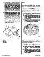
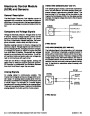
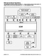
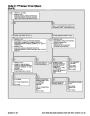
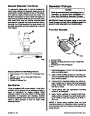
Scan Tools
The ECM can communicate a variety of information
through the DLC connector. This data is transmitted
at a high frequency which requires a scan tool for in-
terpretation.
With an understanding of the data which the tool dis-
plays, and knowledge of the circuits involved, the tool
can be very useful in obtaining information which
would be more difficult or impossible to obtain with
other equipment.
The scan tool is also an easy way to compare the op-
erating parameters of a poorly operating engine with
those of a known good one. For example, a sensor
may shift in value but not set a trouble code. Compar-
ing the senor’s readings with those of the typical scan
tool data readings may uncover the problem.
Scan tools do not make the use of diagnostic charts
unnecessary, nor can they indicate exactly where a
problem is in a particular circuit. Tree charts incorpo-
rate diagnosis procedures using a scan tool where
possible or a Diagnostic Code Tool (non-scan) if a
scan tool is unavailable.
The scan tool has the ability to save time in diagnosis
and prevent the replacement of good parts. The key
to using the scan tool successfully for diagnosis lies
inthetechnician’sabilitytounderstandthesystemhe
is trying to diagnose as well as an understanding of
the scan tool operation and limitations. The techni-
cian should read the tool manufacturer’s operating
manual to become familiar with the tool’s operation.
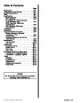
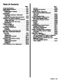
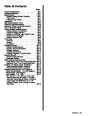
Index
5C-6 - ELECTRONIC FUEL INJECTION (MULTI-PORT AND THROTTLE BODY)
90-823224--2 796
| Categories | Mercury MerCruiser Manuals |
|---|---|
| Tags | Mercury MerCruiser 454 CID, Mercury MerCruiser 502 CID |
| Model Year | 1993, 1994, 1995, 1996, 1997 |
| Download File |
|
| Document File Type | |
| Copyright | Attribution Non-commercial |
(4 votes, average: 4.5 out of 5)
Marine readers have rated 1993 1997 Mercury-MerCruiser GM V8 454 CID 7.4L and 502 CID 8.2L Marine Engines Service Manual Number 16 4.5 out of 5.0 based on 4 product reviews. Hugely helpful service manual! Perfect. Thank you!
Manuals are all Important for Technician
This book is invaluable if you do your own repairs. Great book.
Could not find a copy until a search brought me here.
Excellent print.
Thank you