


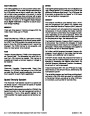


rent output of the alternator does not require regula-
tion, as maximum current output is self-limited by the
design of the alternator. As long as the voltage is reg-
ulated within the prescribed limits, the alternator can-
not produce excessive current. A cut-out relay in the
voltage regulator also is not required, as the rectifier
diodes (which allow current to flow in one direction
only) prevent the battery from discharging back
through the stator.
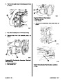
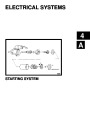
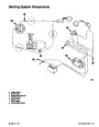
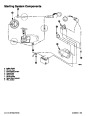
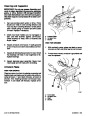
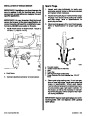
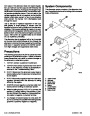
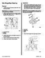
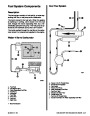
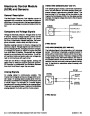
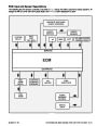
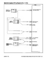
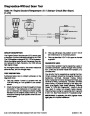
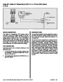
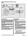
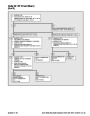
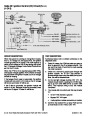
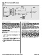
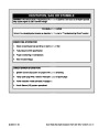
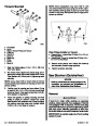
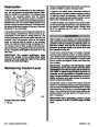
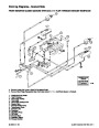
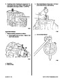
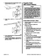
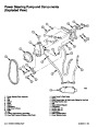
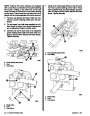
System Components
The alternator system consists of the alternator, bat-
tery,theignitionswitchandthewiringwhichconnects
these components.
h
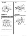
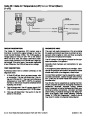
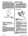
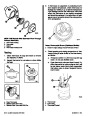
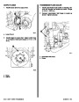
Due to the lack of residual magnetism in the rotor
pole pieces, a small amount of current must be
supplied to the rotor field to initially start the alternator
charging. This is accomplished by means of an exci-
tationcircuitintheregulatorwhichisconnectedtothe
ignitionswitch.Oncethealternatorbeginstoproduce
output, field current is supplied solely by the diode
trio, as explained, preceding.
g
a
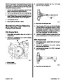
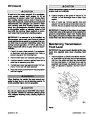
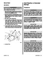
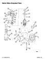
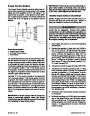
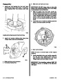
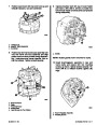
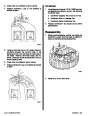
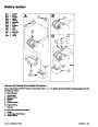
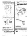
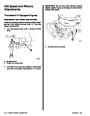
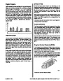
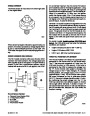
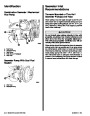
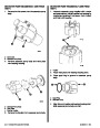
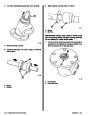
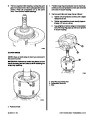
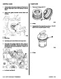
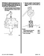
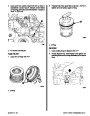
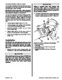
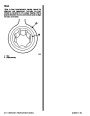
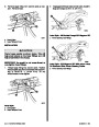
The alternator also is equipped with a fan (mounted
on the rotor shaft) which induces air flow through the
alternator to remove the heat created by the rectifiers
and stator. A capacitor protects the rectifier system
from high voltages and suppresses radio noise.
b
f
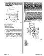
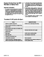
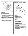
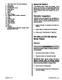
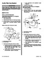
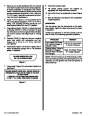
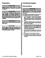
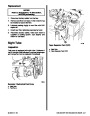
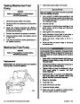
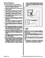
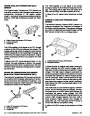
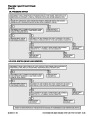
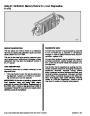
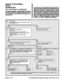
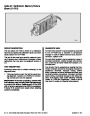
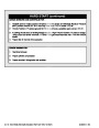
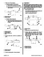
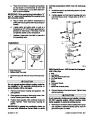
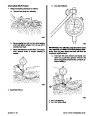
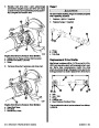
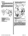
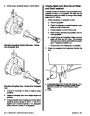
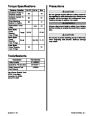
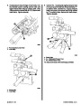
Precautions
The following precautions MUST BE observed when
working on the alternator system. Failure to observe
these precautions may result in serious damage to
the alternator or alternator system.
c
d
1.
2.
DO NOT attempt to polarize the alternator.
DO NOT short across or ground any of the termi-
nals on the alternator, except as specifically in-
structed in the “Troubleshooting Tests.”
e
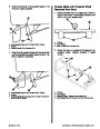
3.
4.
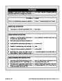
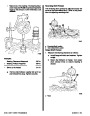
NEVER disconnect the alternator output lead or
battery cables when the alternator is being driven
by the engine.
73079
NEVERdisconnect regulator lead from alternator
regulator terminal when the alternator is being
driven by the engine.
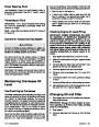
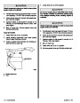
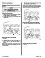
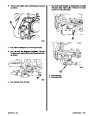
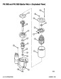
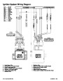
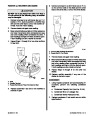
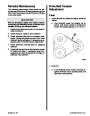
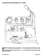
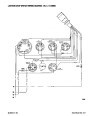
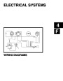
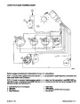
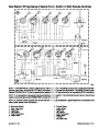
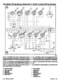
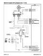
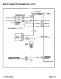
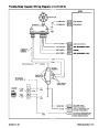
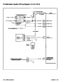
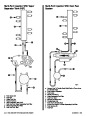
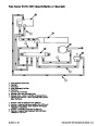
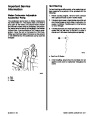
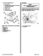
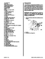
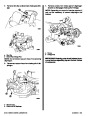
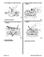
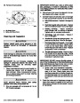
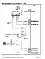
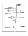
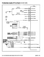
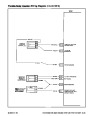
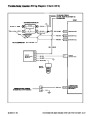
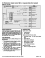
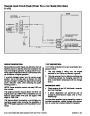
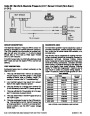
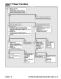
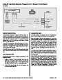
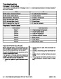
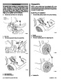
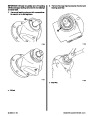
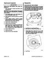
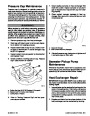
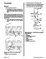
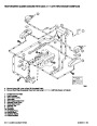
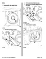
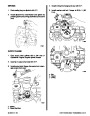
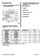
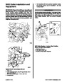
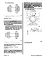
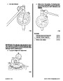
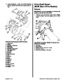
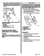
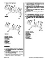
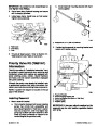
a - Ingition Switch
b - Alternator
c - Starter Motor
d - Ground Stud
e - Battery
f - Circuit Breaker
g - Harness Plug
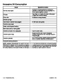
h - Battery Meter
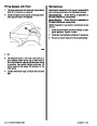
5.
6.
ALWAYS remove negative (–) battery cable from
battery before working on alternator system.
When installing battery, BE SURE to connect the
positive (+) battery cable to the positive (+) bat-
tery terminal and the negative (–) (grounded) bat-
tery cable to negative (–) battery terminal.
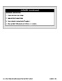
7.
If a charger or booster battery is to be used, BE
SUREtoconnectitinparallelwithexistingbattery
(positive to positive; negative to negative).
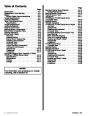
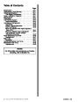
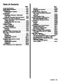
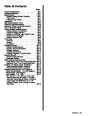
Index
4C-20 - CHARGING SYSTEM
90-823224--2 796
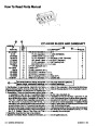
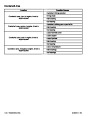
| Categories | Mercury MerCruiser Manuals |
|---|---|
| Tags | Mercury MerCruiser 454 CID, Mercury MerCruiser 502 CID |
| Model Year | 1993, 1994, 1995, 1996, 1997 |
| Download File |
|
| Document File Type | |
| Copyright | Attribution Non-commercial |
(4 votes, average: 4.5 out of 5)
Marine readers have rated 1993 1997 Mercury-MerCruiser GM V8 454 CID 7.4L and 502 CID 8.2L Marine Engines Service Manual Number 16 4.5 out of 5.0 based on 4 product reviews. Hugely helpful service manual! Perfect. Thank you!
Manuals are all Important for Technician
This book is invaluable if you do your own repairs. Great book.
Could not find a copy until a search brought me here.
Excellent print.
Thank you