


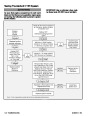


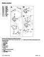


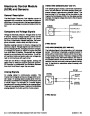


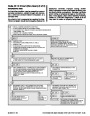


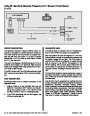


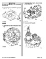
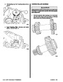


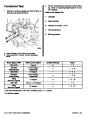


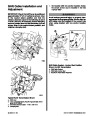


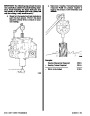


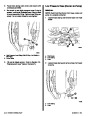


Engine Final Alignment
!
CAUTION
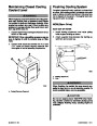
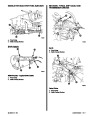
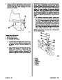
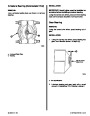
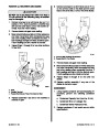
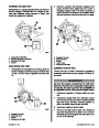
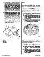
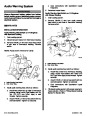
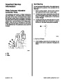
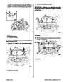
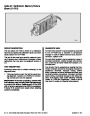
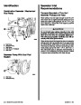
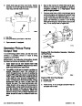
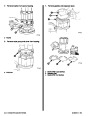
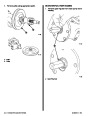
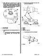
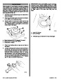
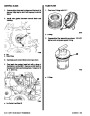
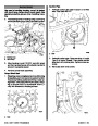
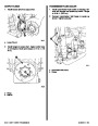
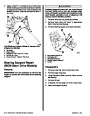
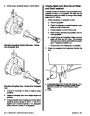
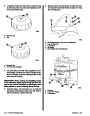
Center lifting eye (located on top of thermostat
housing) is used for engine alignment only. DO
NOT use to lift entire engine.
! CAUTION
To avoid vibration, noise and damage to trans-
mission output shaft oil seal and bearings, en-
gine must be properly aligned.
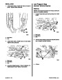
!
CAUTION
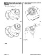
DO NOT allow lifting sling to hook or compress
engine components or damage to them will oc-
cur.
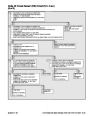
IMPORTANT: Engine alignment MUST BE RE-
CHECKED with boat in the water, fuel tanks filled
and with a normal load on board.
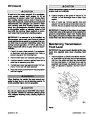
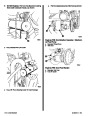
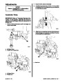
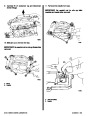
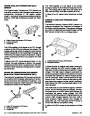
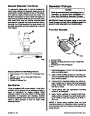
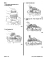
2.
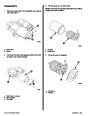
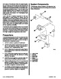
Attach a suitable sling to lifting eyes on engine.
Refer to “Removal” section for location of lift-
ing eyes.
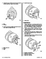
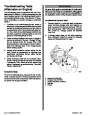
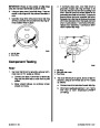
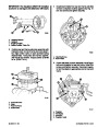
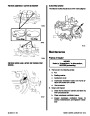
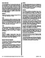
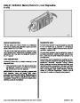
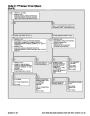
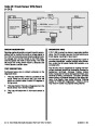
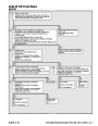
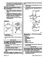
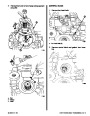
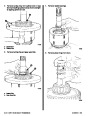
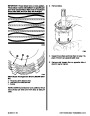
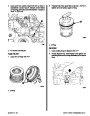
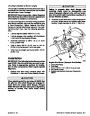
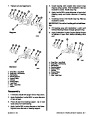
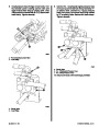
Engine must be aligned so that transmission output
flange and propeller shaft coupler centerlines are
aligned and coupling faces are parallel within .003 in.
(0.07
plings, as well as flexible couplings.
mm).Thisappliestoinstallationswithsolidcou-
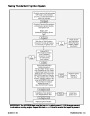
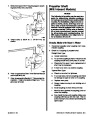
IMPORTANT: Engine bed must position engine
so that a minimum of 1/4 in. (6 mm) up-and-down
adjustment still exists on all four mounts after
performing final alignment. This is necessary to
allow for final engine alignment.
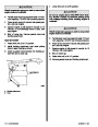
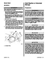
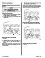
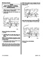
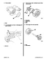
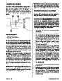
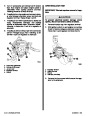
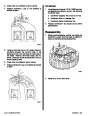
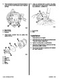
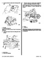
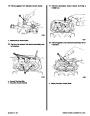
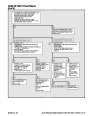
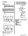
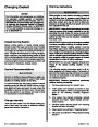
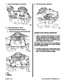
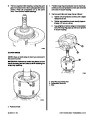
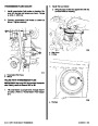
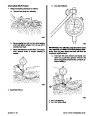
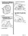
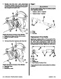
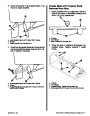
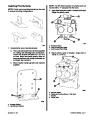
1. Check mating surfaces on transmission output
flange and propeller shaft coupler faces to make
sure they are clean and flat.
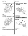
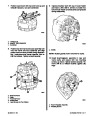
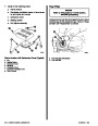
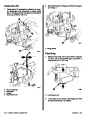
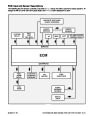
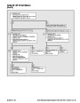
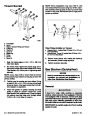
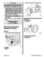
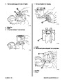
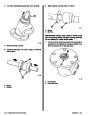
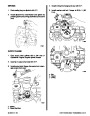
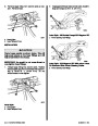
3.
Lift engine into boat and position on engine bed
so that transmission output flange and propeller
shaft coupler are visibly aligned (no gap can be
seen between coupling faces when butted to-
gether). Adjust engine bed height,ifnecessary,
to obtain proper alignment. DO NOT use mount
adjustments to adjust engine position at this time.
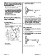
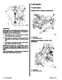
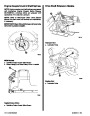
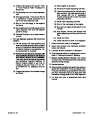
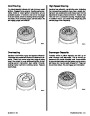
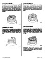
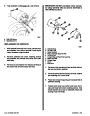
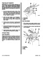
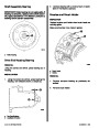
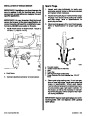
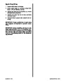
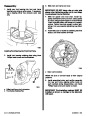
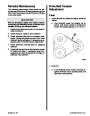
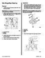
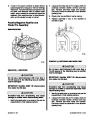
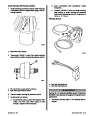
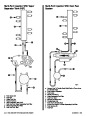
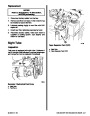
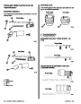
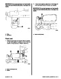
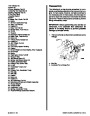
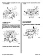
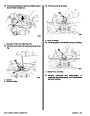
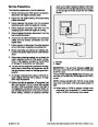
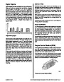
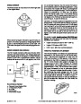
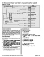
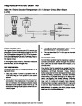
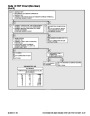
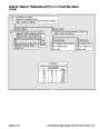
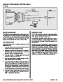
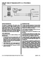
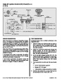
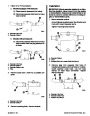
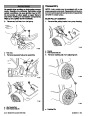
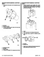
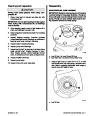
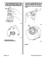
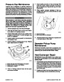
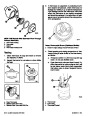
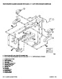
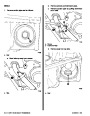
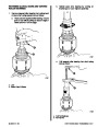
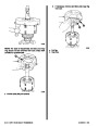
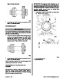
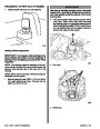
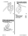
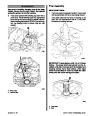
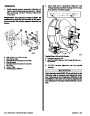
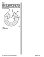
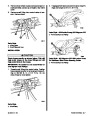
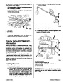
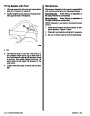
2. Center propeller shaft in shaft log as follows:
a. Push down and then lift shaft as far as it will
move. Then place shaft in the middle of the
movement.
b. Move shaft to port and then to starboard as
far as shaft will move. Then place shaft in the
middle of the movement.
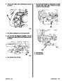
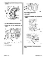
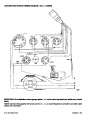
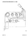
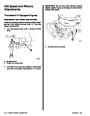
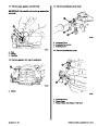
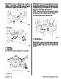
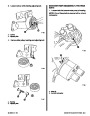
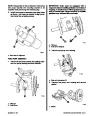
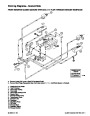
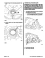
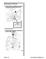
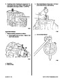
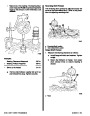
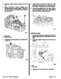
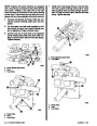
4.
5.
Check all four mounts to ensure that they are still
positioned properly, then fasten mounts to en-
gine bed with appropriate bolts or lag screws and
hardware. Tighten lag bolts/screws securely.
c. With shaft in center of shaft log, as deter-
mined by above procedures “a” and “b,” align
engine to shaft.
Disconnect and remove sling. Proceed to “En-
gine Final Alignment” section following.
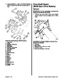
a
d
c
b
72595
a - Up
b - Down
c - Port
d - Starboard
Index
2C-4 - MIE MODELS - VELVET DRIVE TRANSMISSIONS
90-823224--2 796
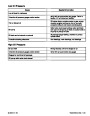
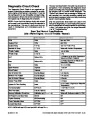
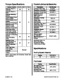
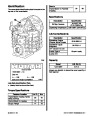
| Categories | Mercury MerCruiser Manuals |
|---|---|
| Tags | Mercury MerCruiser 454 CID, Mercury MerCruiser 502 CID |
| Model Year | 1993, 1994, 1995, 1996, 1997 |
| Download File |
|
| Document File Type | |
| Copyright | Attribution Non-commercial |
(4 votes, average: 4.5 out of 5)
Marine readers have rated 1993 1997 Mercury-MerCruiser GM V8 454 CID 7.4L and 502 CID 8.2L Marine Engines Service Manual Number 16 4.5 out of 5.0 based on 4 product reviews. Hugely helpful service manual! Perfect. Thank you!
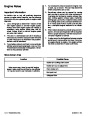
Manuals are all Important for Technician
This book is invaluable if you do your own repairs. Great book.
Could not find a copy until a search brought me here.
Excellent print.
Thank you