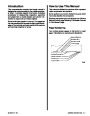


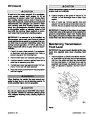
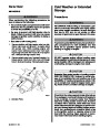
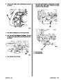
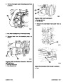


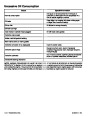


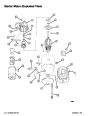


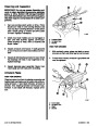


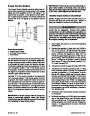
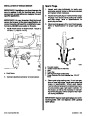


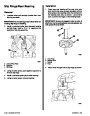


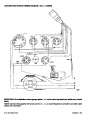
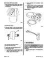


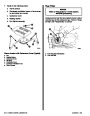
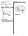


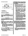


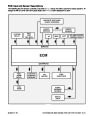


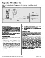
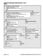
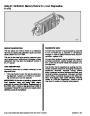


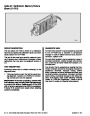
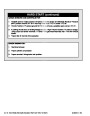


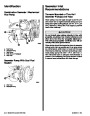
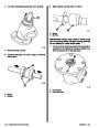


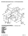


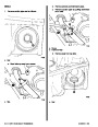


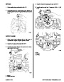
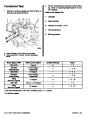
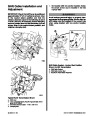


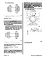
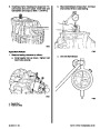
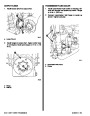


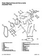


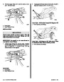


Intake Manifold
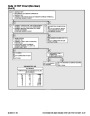
bore. Some of the oil is then used to lubricate cam-
shaft bearings. The remainder of the oil is routed to
the valve lifter oil galleries and No. 1, 2, 3, and 4
crankshaft main bearings by means of individual oil
passages which intersect with the annular grooves.
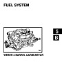
CARBURETED AND THROTTLE BODY
INJECTION
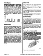
The manifold is of the double level design for efficient
fuel distribution. The upper level of passages feeds
cylinders 2, 3, 5 and 8 while the lower level passages
feed cylinders 1, 4, 6 and 7. All passages are of ap-
proximately equallengthtoassuremoreevenfuel-air
mixture to the cylinders.
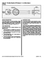
The camshaft bearings have holes which align with
the oil passages or annular grooves in the block and
allowoiltoflowin-betweenthebearingsandthecam-
shaft journals. The oil that is forced out the front end
of the No. 1 camshaft bearing drains down onto the
camshaft drive and keeps it lubricated.
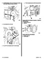
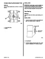
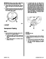
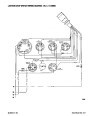
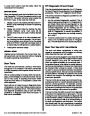
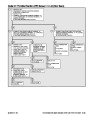
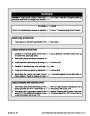
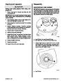
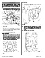
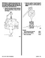
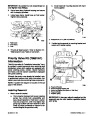
MULTI-PORT INJECTION
The oil which reaches the crankshaft main bearings
is forced through a hole in the upper half of each
bearing and flows in-between the bearings and the
crankshaft journals. Some of the oil is then routed to
the connecting rod bearings through grooves in the
upper half of the crankshaft main bearings and oil
passages in the crankshaft. Oil which is forced out
the ends of the connecting rod bearings and crank-
shaft main bearings is splashed onto the camshaft,
cylinder walls, pistons and piston pins, keeping them
lubricated. Oil which is forced out the front end of the
No.1crankshaftmainbearingalsoassistsinlubricat-
ing the camshaft drive. A baffle plate, mounted on the
bottomofthemainbearingsorintheoilpan,prevents
oil thrown from the crankshaft and connecting rods
from aerating the oil in the oil pan.
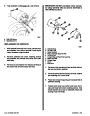
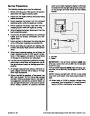
The manifold is a cross flow design, with equal length
runners. Injectors are positioned directly above the
intake ports of each cylinder.
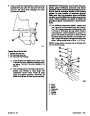
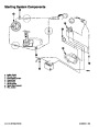
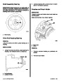
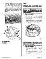
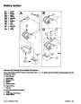
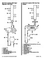
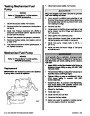
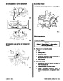
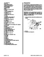
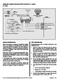
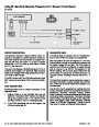
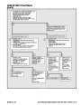
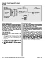
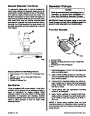
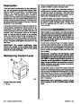
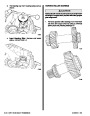
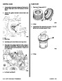
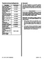
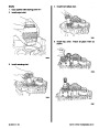
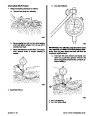
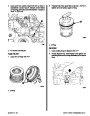
Lubrication System
The engine lubrication system is of the force-feed
type in which oil is supplied under full pressure to the
crankshaft, connecting rods, camshaft bearings and
valve lifters, and is supplied under controlled volume
to the push rods and rocker arms. All other moving
parts are lubricated by gravity flow or splash.
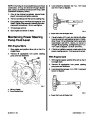
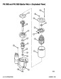
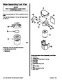
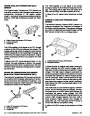
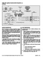
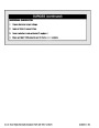
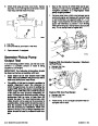
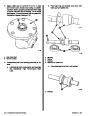
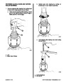
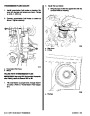
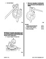
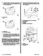
A positive displacement gear-type oil pump is
mounted on the rear main bearing cap and is driven
by an extension shaft from the distributor (which is
driven by the camshaft). Oil from the bottom of the
pump in the rear of the oil pan is drawn into the oil
pump through an oil pickup screen and pipe assem-
bly.
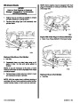
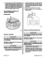
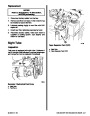
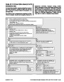
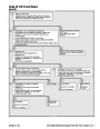
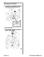
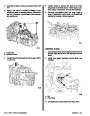
Oil which reaches the valve lifter oil galleries is forced
into each hydraulic valve lifter through holes in the
side of the lifter. From here, the oil is forced through
the metering valve in each of the lifters (which con-
trols the volume of oil flow) and then up through the
push rods to the rocker arms. A hole in each rocker
arm push rod seat allows the oil to pass through the
rocker arm and lubricate the valve train bearing sur-
faces. After lubricating the valve train, oil drains back
to the oil pan through oil return holes in the cylinder
head and block.
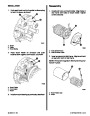
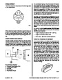
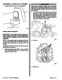
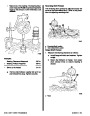
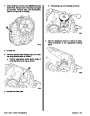
If the screen should become clogged, a relief valve
in the screen will open and continue to allow oil to be
drawn into the system. Once the oil reaches the
pump, the pump forces the oil through the lubrication
system. A spring-loaded relief valve in the pump lim-
its the maximum pump output pressure.
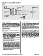
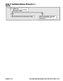
Thedistributorshaftandgearalsoislubricatedbythe
oil flowing through the right valve lifter oil gallery.
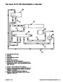
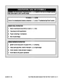
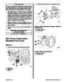
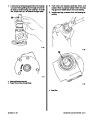
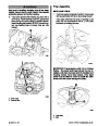
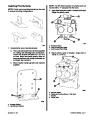
After leaving the pump, the pressurized oil flows
through a full-flow oil filter. On engines with an engine
oil cooler, the oil also flows through the cooler before
returning to the block. A bypass valve allows oil to by-
pass the filter and oil cooler should they become re-
stricted.
Some of the oil, after leaving the oil cooler and/or fil-
ter, is routed to the No. 5 crankshaft main bearing.
The remainder of the oil is routed to the main oil gal-
lery, which is located directly above the camshaft and
runs the entire length of the block. From the main oil
gallery, the oil is routed through individual oil pas-
sages to an annular groove in each camshaft bearing
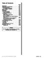
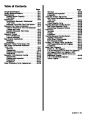
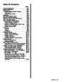
Index
90-823224--2
796
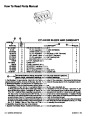
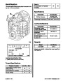
454 CID (7.4L) / 502 CID (8.2L) - 3A-17
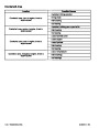
| Categories | Mercury MerCruiser Manuals |
|---|---|
| Tags | Mercury MerCruiser 454 CID, Mercury MerCruiser 502 CID |
| Model Year | 1993, 1994, 1995, 1996, 1997 |
| Download File |
|
| Document File Type | |
| Copyright | Attribution Non-commercial |
(4 votes, average: 4.5 out of 5)
Marine readers have rated 1993 1997 Mercury-MerCruiser GM V8 454 CID 7.4L and 502 CID 8.2L Marine Engines Service Manual Number 16 4.5 out of 5.0 based on 4 product reviews. Hugely helpful service manual! Perfect. Thank you!
Manuals are all Important for Technician
This book is invaluable if you do your own repairs. Great book.
Could not find a copy until a search brought me here.
Excellent print.
Thank you