


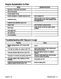


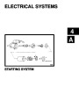


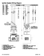
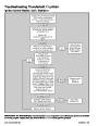


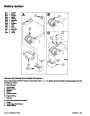


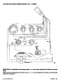
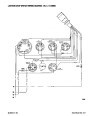
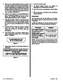


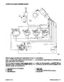
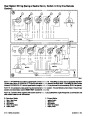
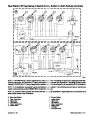
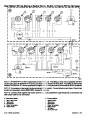
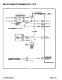
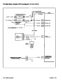


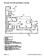
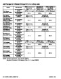


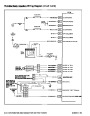


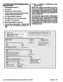
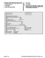
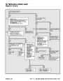


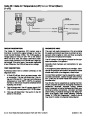


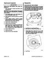


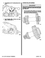


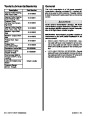


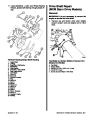
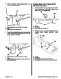


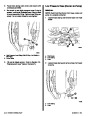
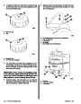


Positive Current Flow
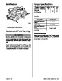
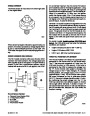
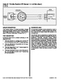
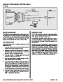
Description
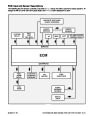
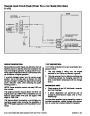
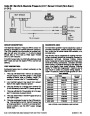
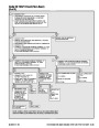
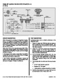
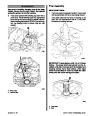
This is a general description of the positive current
flow,fromthebatteryandthroughthesystemuntilthe
starter motor cranks.
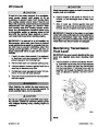
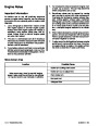
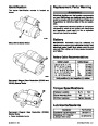
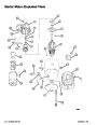
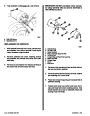
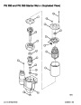
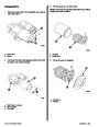
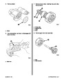
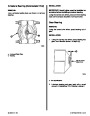
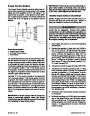
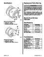
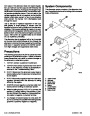
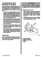
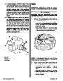
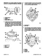
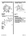
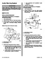
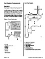
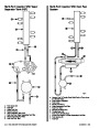
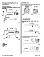
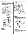
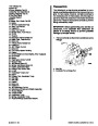
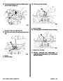
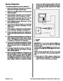
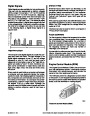
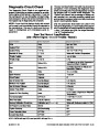
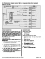
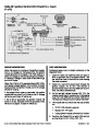
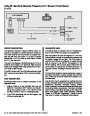
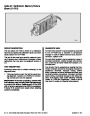
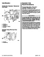
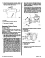
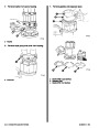
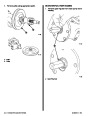
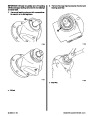
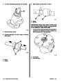
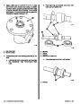
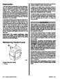
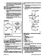
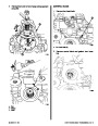
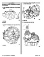
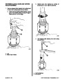
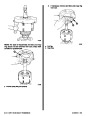
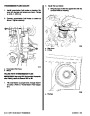
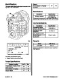
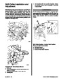
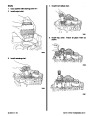
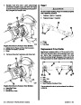
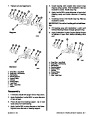
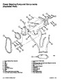
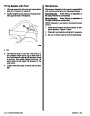
The Permanent Magnet Gear Reduction (PG200
and PG250) starter motors feature small permanent
magnets mounted inside the field frame (NOTE: The
actual configuration of these magnets differs be-
tween the PG200, PG250 and PG260; the field
frames with permanent magnets are not inter-
changeable. Otherwise, the units are similar.) These
magnets take the place of current-carrying field coils
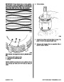
mounted on iron pole pieces. Internal gear reduction,
approximately 4 to 1, through planetary gears results
in armature speeds in the 7000 RPM range. The ar-
mature and drive shaft are mounted on roller or ball
bearings in place of bushings. The solenoid switch,
plunger, return spring, and shift lever are permanent-
ly mounted in the drive housing.
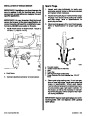
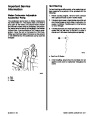
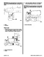
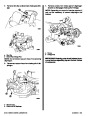
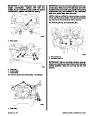
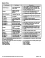
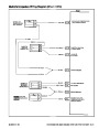
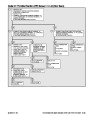
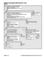
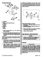
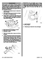
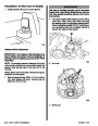
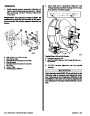
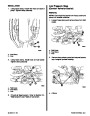
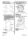
•
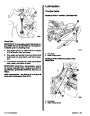
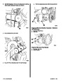
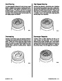
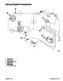
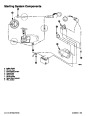
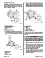
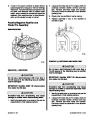
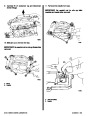
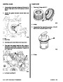
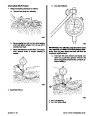
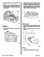
Battery to the solenoid switch (on starter)
(RED battery cable).
•
•
•
Solenoid switch to circuit breaker (RED).
Circuit breaker to wire junction (RED-PUR).
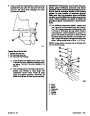
Wire junction to wiring harness plug
(RED-PUR) terminal 6.
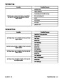
•
•
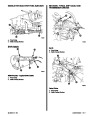
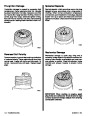
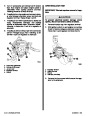
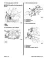
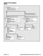
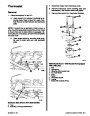
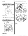
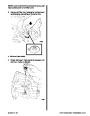
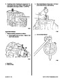
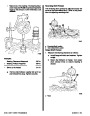
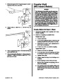
Wiring harness plug to 20 amp fuse
(RED-PUR).
20 amp fuse to ignition switch terminal I
(RED-PUR). At this point ignition switch is
turned to START.
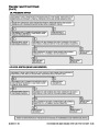
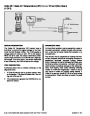
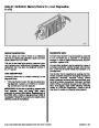
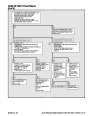
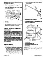
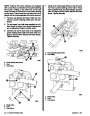
!
CAUTION
•
•
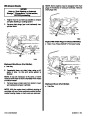
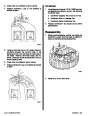
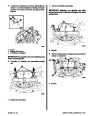
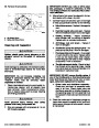
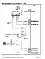
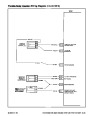
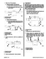
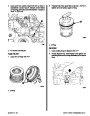
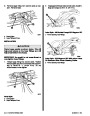
Ignition switch terminal B to terminal S.
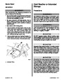
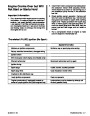
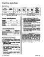
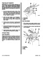
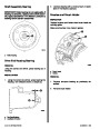
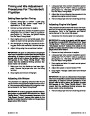
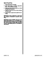
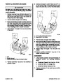
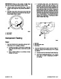
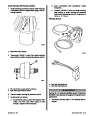
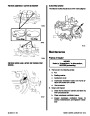
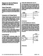
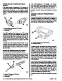
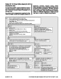
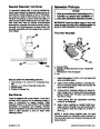
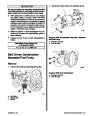
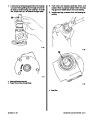
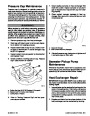
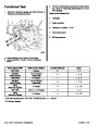
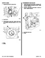
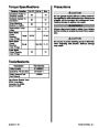
The starter motor is designed to operate under
great overload and produce a high horsepower
for its size. It can do this only for a short time,
since considerable heat accumulates and can
cause serious damage. For this reason, the
cranking motormustneverbeusedformorethan
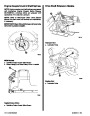
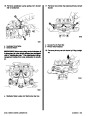
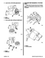
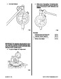
Ignition switch terminal S to neutral start
switch (YEL-RED). NEUTRAL START SWITCH
MUST BE AT NEUTRAL POSITION.
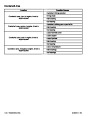
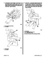
•
•
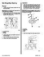
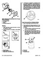
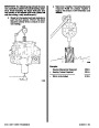
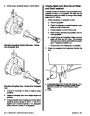
Neutral start switch to wiring harness plug
terminal 7 (YEL-RED).
30
seconds at any one time. Cranking should not
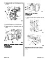
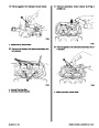
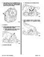
Wiring harness plug to starter solenoid(small
terminal) (YEL-RED). Also ensure that black
(small terminal) wire is grounded.
be repeated without a pause of at least 2 minutes
to permit the heat to escape.
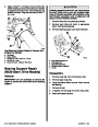
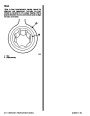
•
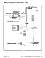
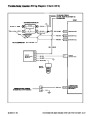
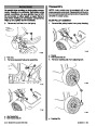
Starter solenoid is now “closed,” completing
circuit between large terminal (RED-PUR) and
other large terminal (YEL-RED), causing
starter motor to crank.
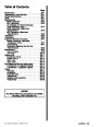
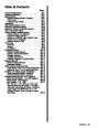
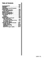
Index
90-823224--2 796
STARTING SYSTEM - 4A-17
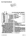
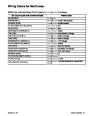
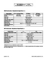
| Categories | Mercury MerCruiser Manuals |
|---|---|
| Tags | Mercury MerCruiser 454 CID, Mercury MerCruiser 502 CID |
| Model Year | 1993, 1994, 1995, 1996, 1997 |
| Download File |
|
| Document File Type | |
| Copyright | Attribution Non-commercial |
(4 votes, average: 4.5 out of 5)
Marine readers have rated 1993 1997 Mercury-MerCruiser GM V8 454 CID 7.4L and 502 CID 8.2L Marine Engines Service Manual Number 16 4.5 out of 5.0 based on 4 product reviews. Hugely helpful service manual! Perfect. Thank you!
Manuals are all Important for Technician
This book is invaluable if you do your own repairs. Great book.
Could not find a copy until a search brought me here.
Excellent print.
Thank you