
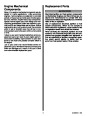


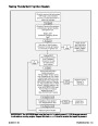


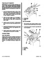


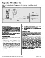


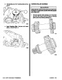


ENGINE MOUNT ADJUSTMENT WAS
DISTURBED DURING SERVICE
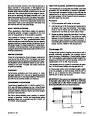
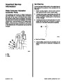
IMPORTANT: Be sure that boat does not move
once reading has been taken from input shaft
flange, as this reading establishes a reference
point for aligning drive shaft and engine follow-
ing. If boat is moved, reference point may be al-
tered and subsequently,improperdriveshaftand
engine alignment may occur. Alignment tool
MUST BE in place during entire alignment proce-
dure if drive unit is not installed.
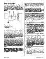
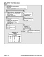
NOTE: A Universal Protractor is recommended for
measuring the angles in the following steps.
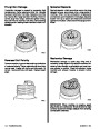
IMPORTANT: In the following steps, the protrac-
tor readings will be taken off of vertical and hori-
zontal surfaces; therefore, both the 0 degree and
the 90 degree marks will be used. It should be
kept in mind that these are reference marks only
and the assigned numbers should be ignored. It
is only necessary to determine the number of de-
grees and to which side (left or right) of the refer-
ence marks the indicator needle rests. PRO-
TRACTOR MUST BE VIEWED FROM THE SAME
SIDE OF POWER PACKAGE THROUGHOUT IN-
STALLATION.
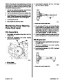
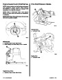
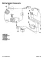
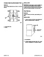
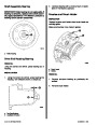
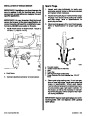
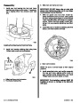
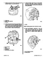
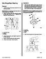
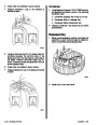
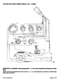
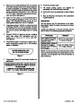
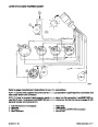
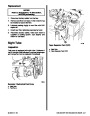
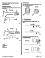
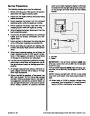
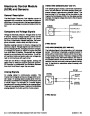
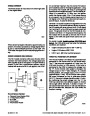
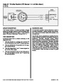
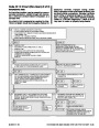
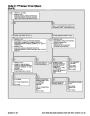
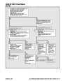
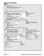
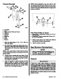
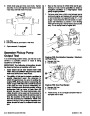
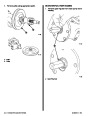
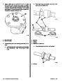
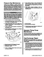
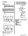
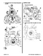
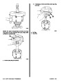
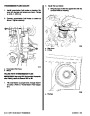
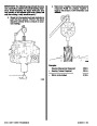
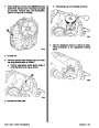
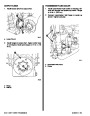
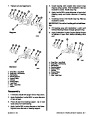
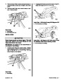
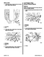
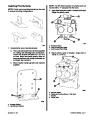
a
b
a
c
72592
a
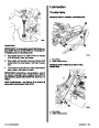
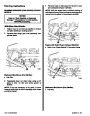
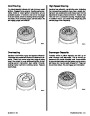
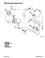
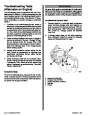
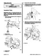
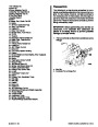
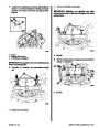
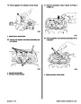
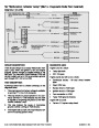
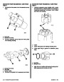
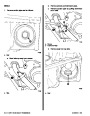
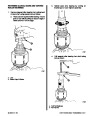
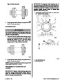
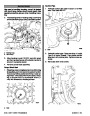
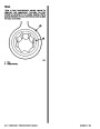
a - Indicator Shaft Flange
b - Protractor
c - Indicator Needle
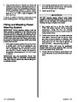
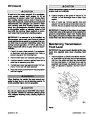
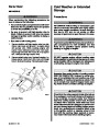
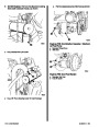
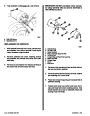
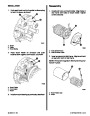
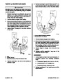
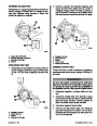
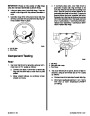
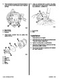
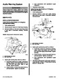
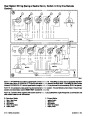
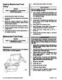
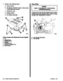
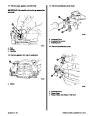
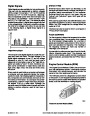
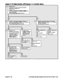
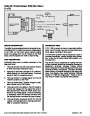
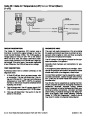
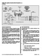
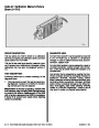
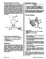
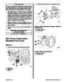
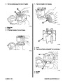
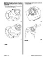
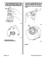
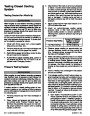
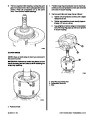
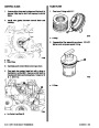
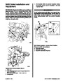
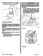
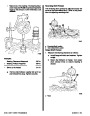
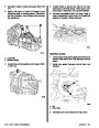
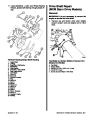
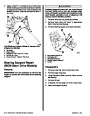
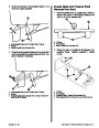
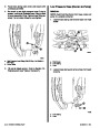
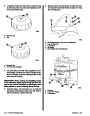
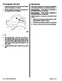
NOTE: For ease of installation we recommend the
use of a chain leveler in the following steps.
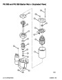
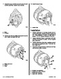
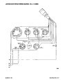
72429
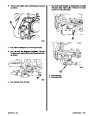
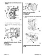
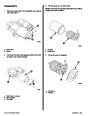
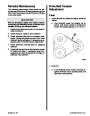
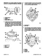
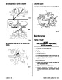
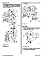
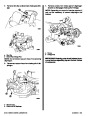
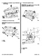
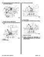
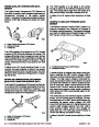
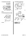
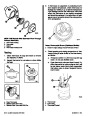
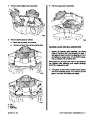
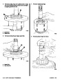
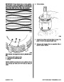
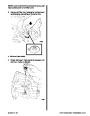
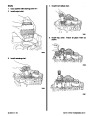
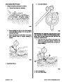
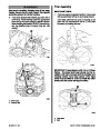
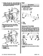
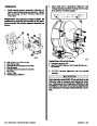
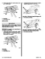
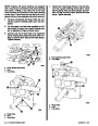
3.
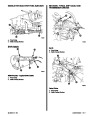
Adjust engine mounts so that an equal amount of
up and down adjustment exists.
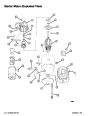
a - Reference Marks
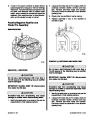
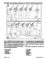
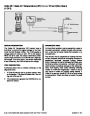
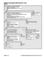
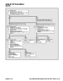
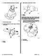
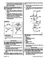
4.
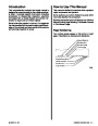
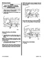
Attach a suitable lifting chain to lifting eyes on en-
gine and adjust so that engine will be level when
suspended, then place engine into its approxi-
mate position (in boat) using an overhead hoist.
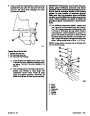
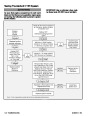
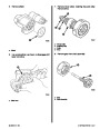
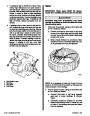
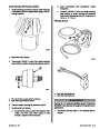
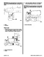
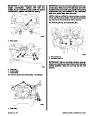
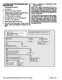
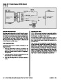
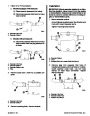
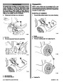
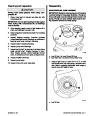
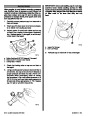
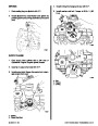
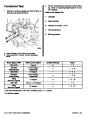
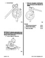
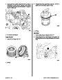
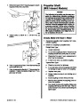
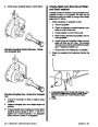
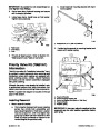
1.
2.
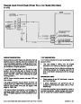
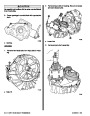
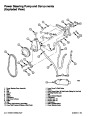
Refer to Section 8E - “Drive Shaft Models/Propel-
ler Shaft,” and remove drive shaft.
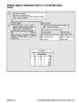
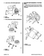
Position base of protractor against input shaft
flange, as shown. NOTE and RECORD the num-
ber of degrees and to which side of the reference
mark the indicator needle has moved in the fol-
lowing chart.
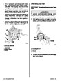
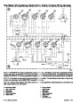
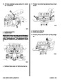
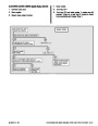
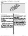
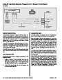
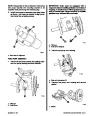
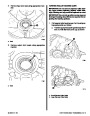
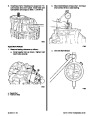
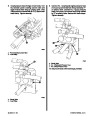
5.
Refer to Section 8E - “Drive Shaft Models/Propel-
ler Shaft,” and install drive shaft while observing
precautions in Section 8D, especially about
aligning gimbal bearing U-joint centerlines with
extension drive shaft U-joint centerlines at bear-
ing support input shaft. DO NOT install shields at
this time.
Reading from Step 1. __________ degrees to the
_________
side of reference mark.
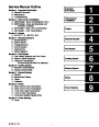
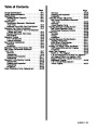
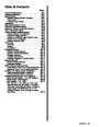
Index
2B-6 - BRAVO AND BLACKHAWK DRIVES WITH DRIVESHAFT EXTENSIONS
90-823224--2 796
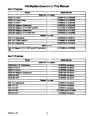
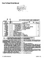
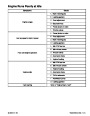
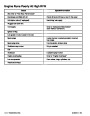
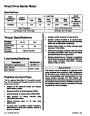
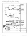
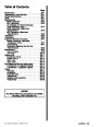
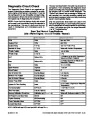
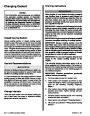
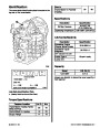
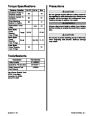
| Categories | Mercury MerCruiser Manuals |
|---|---|
| Tags | Mercury MerCruiser 454 CID, Mercury MerCruiser 502 CID |
| Model Year | 1993, 1994, 1995, 1996, 1997 |
| Download File |
|
| Document File Type | |
| Copyright | Attribution Non-commercial |
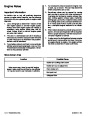
(4 votes, average: 4.5 out of 5)
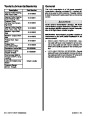
Marine readers have rated 1993 1997 Mercury-MerCruiser GM V8 454 CID 7.4L and 502 CID 8.2L Marine Engines Service Manual Number 16 4.5 out of 5.0 based on 4 product reviews. Hugely helpful service manual! Perfect. Thank you!
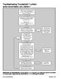
Manuals are all Important for Technician
This book is invaluable if you do your own repairs. Great book.
Could not find a copy until a search brought me here.
Excellent print.
Thank you