


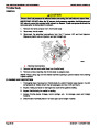


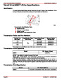


DIAGNOSTICS
SERVICE MANUAL NUMBER 24
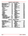
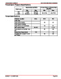
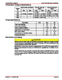
ECM Connector and EFI Symptoms Chart
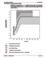
The following charts will aid in diagnosis of symptoms. These voltages were derived from
a known good engine. The voltages shown were done with the electrical system intact and
operational. These are voltage requirements to operate the different circuits.
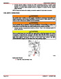
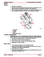
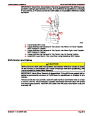
CAUTION
Do not attempt to obtain these voltages by probing wires and connectors. Serious
damage could result in loss of engine operation or wiring damage. Voltages can
vary with battery conditions.
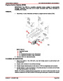
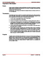
In the following J-1 and J-2 Circuit/Symptom Charts only those pins which are used by the
ECM are shown. Pin numbers not listed are not used.
NOTE: All pins are not used on all models.
IMPORTANT: The following conditions must be met before testing.
1.
2.
3.
Engine at operating temperature.
Ignition on or engine running.
Scan tool not connected.
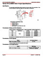
THESE NOTES APPLY TO FOLLOWING ECM CONNECTOR AND SYMPTOM CHARTS.
The “B+” Symbol indicates a system voltage (battery).
NOTE: 1 Battery voltage for first two seconds, then 0 volts.
NOTE: 2 Varies with temperature.
NOTE: 3 Varies with manifold vacuum.
NOTE: 4 Varies with throttle movement.
NOTE: 5 Less than .5 volt (500 mV).
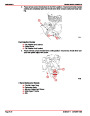
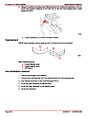
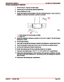
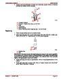
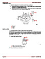
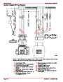
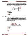
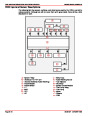
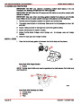
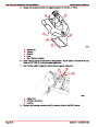
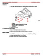
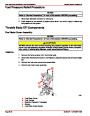
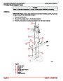
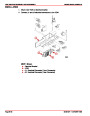
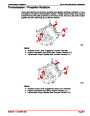
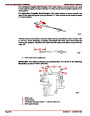
J-1 Circuits with MEFI 1 and MEFI 2
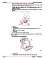
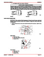
a
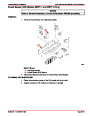
J-1 Front Pin 32 Pin Input Connector
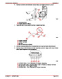
a - Shaded Area Denotes Pin Connector Location Used On Terminal
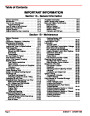
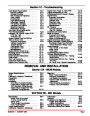
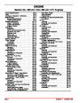
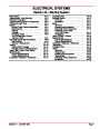
Index
Page 5G-6
90-861327--1 OCTOBER 1999
| Categories | Mercury MerCruiser Manuals |
|---|---|
| Tags | Mercury MerCruiser 305 CID, Mercury MerCruiser 350 CID |
| Model Year | 1998, 1999, 2000, 2001 |
| Download File |
|
| Document File Type | |
| Copyright | Attribution Non-commercial |
(1 votes, average: 4 out of 4)
Marine readers have rated Mercury MerCruiser Engines Service Manual Number 24 GM V-8 305 CID 350 CID 4.0 out of 4.0 based on 1 product reviews. Great performance engine.
Class 1