


SERVICE MANUAL NUMBER 24
FUEL INJECTION DESCRIPTIONS AND SYSTEM OPERATION
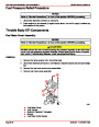
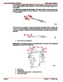
RUN MODE
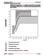
When the engine is started and rpm is above 300, the system operates in the run mode. The
ECM will calculate the desired air/fuel ratio based on these ECM inputs: rpm, Manifold Abso-
lute Pressure (MAP) sensor, and Engine Coolant Temperature (ECT) sensor . Higher en-
gine load (from MAP) and colder engine temperature (from ECT) requires more fuel, or a
richer air/fuel ratio.
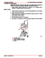
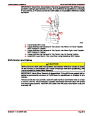
ACCELERATION MODE
The ECM looks at rapid changes in Throttle Position (TP) and provides extra fuel by increas-
ing the injector pulse width.
FUEL CUTOFF MODE
No fuel is delivered by the injectors when the ignition is OFF, to prevent dieseling. Also, fuel
pulses are not delivered if the ECM receives no distributor reference pulses, which means
the engine is not running. The fuel cutoff mode is also enabled at high engine rpm, as an
overspeed protection for the engine. When cutoff is in effect due to high rpm, injection pulses
will resume after engine rpm drops slightly.
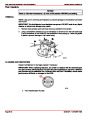
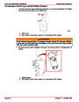
DECELERATION MODE
The IAC is similar to a carburetor dashpot. It provides additional air when the throttle is
rapidly moved to the idle position to prevent the engine from dying.
REV-LIMIT MODE
A fuel cutoff function is enabled at higher engine rpm. When the ECM senses that the engine
has exceeded its specified maximum rpm, no fuel is delivered by the injectors. After the rpm
drops below the specified maximum rpm, the ECM will resume fuel delivery.
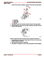
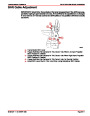
MEFI-3 LOAD ANTICIPATION MODE
The Load Anticipation mode is available on MIE inboard engines only. The function is used
to help inboard engines during shifting. An electrical signal from the neutral safety switch
(on the transmission) is used to tell the ECM if the switch is closed or open. In neutral gear,
the neutral safety switch is closed (signal grounded). When shifting into gear, the switch
opens (signal open).
When the transmission is shifted into gear, the open signal causes the ECM to add a cali-
brated amount of bypass air with the IAC. This is done to increase the load handling capabili-
ty of the engine when going into gear on larger boats. When shifting back into neutral gear,
the additional IAC bypass air is removed in an attempt to limit engine rpm flares. The amount
of IAC air used is constantly monitored by the ECM. After the transmission is shifted, and
the engine has stabilized, the ECM calculates an ‘error band’ from the Moving Desired rpm
mode and adjusts the Load Anticipation mode IAC count accordingly. This allows the ECM
to ‘learn’ the best IAC bypass air position to use for shift conditions in each particular boat.
Index
90-861327
OCTOBER 1999
Page 5D-25
| Categories | Mercury MerCruiser Manuals |
|---|---|
| Tags | Mercury MerCruiser 305 CID, Mercury MerCruiser 350 CID |
| Model Year | 1998, 1999, 2000, 2001 |
| Download File |
|
| Document File Type | |
| Copyright | Attribution Non-commercial |
(1 votes, average: 4 out of 4)
Marine readers have rated Mercury MerCruiser Engines Service Manual Number 24 GM V-8 305 CID 350 CID 4.0 out of 4.0 based on 1 product reviews. Great performance engine.
Class 1