


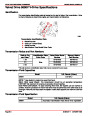


FUEL DELIVERY SYSTEM FOR CARBURETED ENGINES
SERVICE MANUAL NUMBER 24
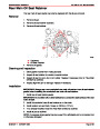
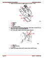
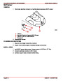
Fuel Delivery System
Recommendations
WARNING
Boating standards (NMMA, ABYC, etc.) and Coast Guard regulations must be
adhered to when installing fuel delivery system
GENERAL
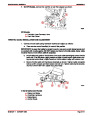
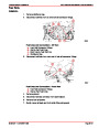
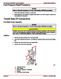
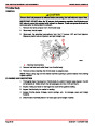
The fuel tank is an integrated component of the boat. Refer to the special information on
service and maintenance that you have received from the tank manufacturer.
NOTE: On Ski Boat Applications: If during testing for a particular application, you experi-
ence fuel starvation in sharp high speed turns, baffles or a fuel sump may be needed in the
tank to help correct this condition.
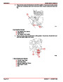
Only a few points related to function and safety are listed here. Refer to boating standards
(NMMA, ABYC, etc.) and Coast Guard regulations for complete guidelines:
•
•
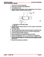
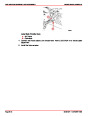
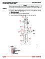
All connections should be on the upper side of the tank.
The drain plug at the lowest point on the tank serves to permit the removal of water
and sediment.
•
•
The filler pipe outer diameter should be at least 2 in. (51 mm).
The tank breather pipe must have an inner diameter of at least 1/2 in. (13mm) and
must be fitted with a swan neck to prevent water from entering the tank.
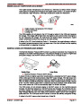
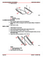
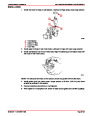
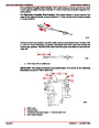
It is recommended that the exact route and length of the fuel lines be established at the first
installation of the engine to prevent problems later in connecting them to the engine.
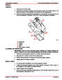
All fuel lines must be well secured. The holes where the lines run through the bulkheads
should be carefully rounded off or protected with rubber grommets. This prevents damage
to the lines from abrasion.
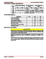
The following, but not limited to the following, additional fuel connection related points,
applying to all engines unless otherwise stated, must be considered [Refer to boating
standards (NMMA, ABYC, etc.) and Coast Guard regulations for complete guidelines]:
1.
2.
3.
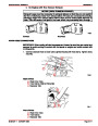
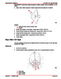
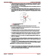
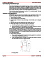
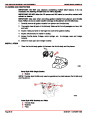
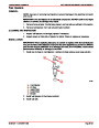
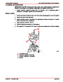
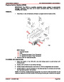
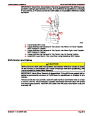
Fuel tank should be mounted below carburetor level (if possible) or gravity feed may
cause carburetor fuel inlet needle to unseat and flooding may result.
Fuel pickup should be at least 1 in. (25mm) from the bottom of fuel tank to prevent pick-
ing up impurities.
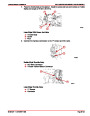
Fuel lines used must be Coast Guard approved (USCG Type A1).
Diameter of fittings and lines must not be smaller than 5/16 in. (8 mm) inside diameter (I.D.)
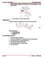
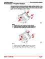
4.
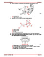
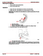
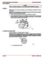
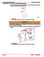
On Multi-Engine Installations: It is best to use a fuel pickup and supply line for each
engine. If a single pickup and line is used, line must not be smaller than 1/2 in. (13mm)
I.D.
Page 5A-4
90-861327--1 OCTOBER 1999
| Categories | Mercury MerCruiser Manuals |
|---|---|
| Tags | Mercury MerCruiser 305 CID, Mercury MerCruiser 350 CID |
| Model Year | 1998, 1999, 2000, 2001 |
| Download File |
|
| Document File Type | |
| Copyright | Attribution Non-commercial |
(1 votes, average: 4 out of 4)
Marine readers have rated Mercury MerCruiser Engines Service Manual Number 24 GM V-8 305 CID 350 CID 4.0 out of 4.0 based on 1 product reviews. Great performance engine.
Class 1