


SERVICE MANUAL NUMBER 24
CHARGING SYSTEM
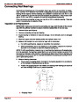
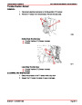
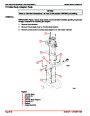
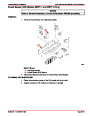
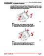
SENSING CIRCUIT
1.
2.
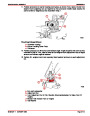
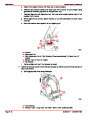
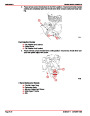
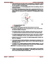
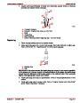
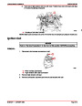
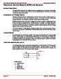
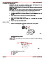
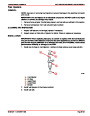
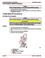
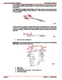
Unplug RED/PURPLE lead from voltage regulator.
Connect positive (+) voltmeter lead to red/purple lead and negative (–) voltmeter lead
to ground terminal.
3.
Voltmeter should indicate battery voltage. If battery voltage is not present, check sens-
ing circuit (red/purple lead) for loose or dirty connection or damaged wiring.
d
a
e
c
72786
b
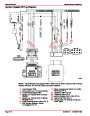
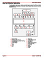
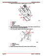
Typical
a - Output Wire - ORANGE
b - Excitation Wire - PURPLE
c - Sensing Wire - RED/PURPLE
d - Voltmeter (0-20 Volts)
e - Ground
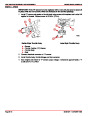
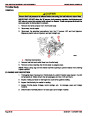
Component
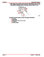
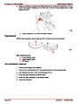
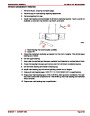
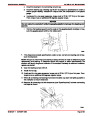
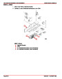
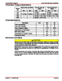
ROTOR
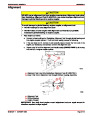
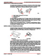
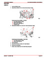
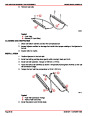
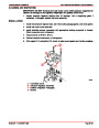
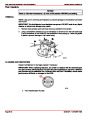
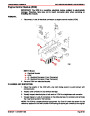
1.
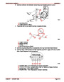
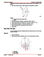
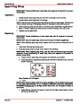
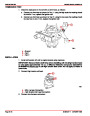
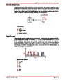
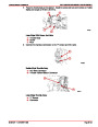
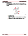
Test rotor field circuit for opens, shorts or high resistance (Test 1), using an ohmmeter
(set on R x1 scale), as follows:
a
b
72831
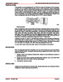
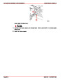
Testing Rotor Field Circuit
a - Test 1
b - Test 2
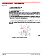
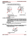
a. Connect one ohmmeter lead to each slip ring.
b. Ohmmeter reading should be 4.2 to 5.5 ohms with rotor at room temperature
°F (21-26°C).
70-80
90-861327--1
OCTOBER 1999
Page 4C-11
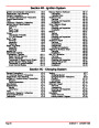
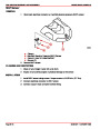
| Categories | Mercury MerCruiser Manuals |
|---|---|
| Tags | Mercury MerCruiser 305 CID, Mercury MerCruiser 350 CID |
| Model Year | 1998, 1999, 2000, 2001 |
| Download File |
|
| Document File Type | |
| Copyright | Attribution Non-commercial |
(1 votes, average: 4 out of 4)
Marine readers have rated Mercury MerCruiser Engines Service Manual Number 24 GM V-8 305 CID 350 CID 4.0 out of 4.0 based on 1 product reviews. Great performance engine.
Class 1