


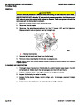
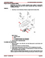


IGNITION SYSTEM
SERVICE MANUAL NUMBER 24
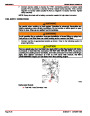
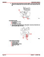
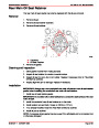
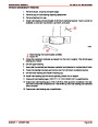
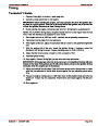
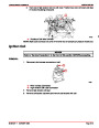
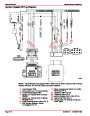
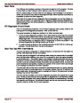
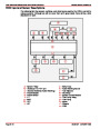
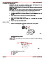
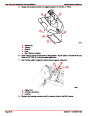
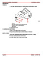
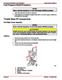
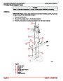
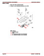
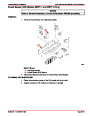
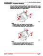
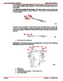
Ignition System Wiring Diagram
TO ENGINE HARNESS
TO DISTRIBUTOR
13
3
1
8
11
9
10
1
2
12
6
3
4
5
7
K
L
A
B
C
D
E
G
H
I
F
J
E
C BA
D
KNOCK
CONTROL
MODULE
IGNITION
CONTROL
MODULE
75456
NOTE: 1 Alpha Models Are Equipped With A Shift Cut-Out Switch. 305 and 350 cid Bravo
Models Will Have Two BLACK Leads Connected Together.
1
2
3
4
- Knock Sensor Wire
8 - Water Temperature Switch (For Audio
Warning) (Pin H)
9 - Distributor Wire (Pin G)
10 - Distributor Wire (Pin I)
11 - Ignition Module Grd (–) Wire (Pin J)
12 - Tachometer Wire (Pin L)
13 - Timing Lead (For Setting Timing and
Other Tests)
- Ground Wire (–) For Knock Module
- Knock Module Signal Wire
- Battery (+) Positive Wire To Knock
Module
- Battery (+) Positive Wire To Ignition
Module(Pin C)
- Audio Warning System Wire (Pin D)
- Shift System Interrupt Switch
(If Equipped (Pin E)
5
6
7
Page 4B-14
90-861327--1 OCTOBER 1999
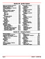
| Categories | Mercury MerCruiser Manuals |
|---|---|
| Tags | Mercury MerCruiser 305 CID, Mercury MerCruiser 350 CID |
| Model Year | 1998, 1999, 2000, 2001 |
| Download File |
|
| Document File Type | |
| Copyright | Attribution Non-commercial |
(1 votes, average: 4 out of 4)
Marine readers have rated Mercury MerCruiser Engines Service Manual Number 24 GM V-8 305 CID 350 CID 4.0 out of 4.0 based on 1 product reviews. Great performance engine.
Class 1