


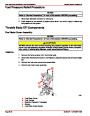


SERVICE MANUAL NUMBER 24
FUEL INJECTION DESCRIPTIONS AND SYSTEM OPERATION
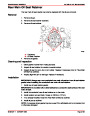
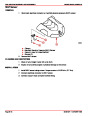
Modes Of Operation
DISTRIBUTOR MODULE MODE (MEFI 1 AND MEFI 2 ONLY)
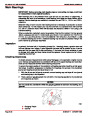
The ignition system operates independent of the ECM. The distributor module module in
the distributor maintains a base ignition timing and is able to advance timing to a total of 27
degrees. This mode is in control when a Code 42 is detected while engine is running and
will have a noticeable affect on engine operation.
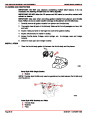
The following describes IC operation during cranking and when the engine starts running.
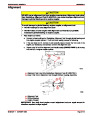
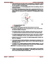
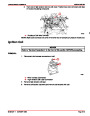
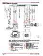
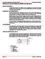
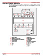
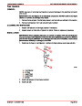
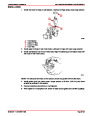
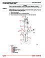
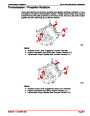
To help understand how IC circuits operate, a relay with a double set of contact points is
shown in the IC module (refer to the figures “Ignition Control Mode” and “ECM Control
Mode”). Solid state circuitry is used in the module, but showing the relay makes it easier to
visualize how the IC module functions.
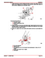
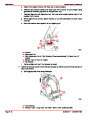
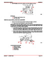
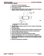
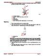
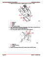
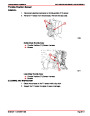
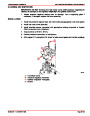
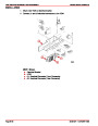
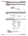
During cranking, the relay is in the de-energized position (see figure “Distributor Module
Mode”). This connects the pickup coil to the base of the transistor via the signal converter.
When the pickup coil applies a positive voltage to the transistor, the transistor turns ON.
When voltage is removed, the transistor turns OFF. When the transistor turns ON, current
flows through the primary winding of the ignition coil. When it turns OFF, the primary current
stops and a spark is developed at the spark plug. A small amount of advance is built into
the IC module via a timing circuit, in case the engine remains in the ignition module timing
mode.
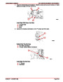
With the relay de-energized, a set of contacts (shown closed) would ground the IC line sig-
nal.
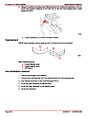
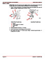
ECM CONTROL MODE
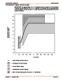
The ECM control mode controls the ignition timing. The ECM calculates the desired ignition
timing based on information it gets from its input sensors.
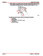
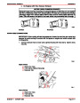
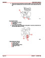
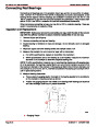
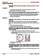
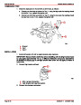
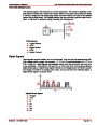
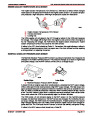
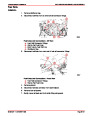
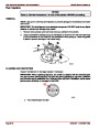
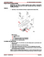
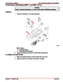
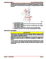
(MEFI 1 and MEFI 2) When the engine rpm reaches a predetermined value (for this exam-
ple, 300 rpm), the ECM considers the engine running and applies five volts on the bypass
line to the IC module. This energizes the relay and causes the contacts from the pickup coil
as well as the grounding contacts for the IC line to open (see figure “ECM Control Mode”).
This connects the IC line to the base of the transistor, and bypasses the ignition module tim-
ing control.
The IC system is now controlled by the IC signal from the ECM and the time at which the
spark occurs can be determined by a variable time circuit in the ECM.
Index
90-861327
OCTOBER 1999
Page 5D-21
| Categories | Mercury MerCruiser Manuals |
|---|---|
| Tags | Mercury MerCruiser 305 CID, Mercury MerCruiser 350 CID |
| Model Year | 1998, 1999, 2000, 2001 |
| Download File |
|
| Document File Type | |
| Copyright | Attribution Non-commercial |
(1 votes, average: 4 out of 4)
Marine readers have rated Mercury MerCruiser Engines Service Manual Number 24 GM V-8 305 CID 350 CID 4.0 out of 4.0 based on 1 product reviews. Great performance engine.
Class 1