


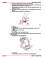


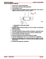


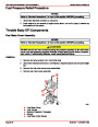


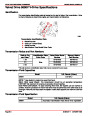


IGNITION SYSTEM
SERVICE MANUAL NUMBER 24
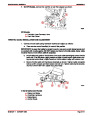
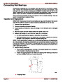
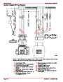
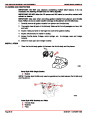
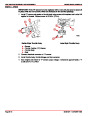
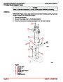
TESTING KNOCK MODULE AND KNOCK SENSOR
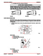
NOTE: A digital volt-ohmmeter (DVOM) and an unpowered test light (low power test light
-
300mA or less) are needed to conduct the following test.
WARNING
Avoid fire or explosion. Ensure that engine compartment is well ventilated and gas-
oline vapors are not present when performing electrical tests inside the engine
compartment. Sparks generated by electrical tests could ignite gasoline vapors
causing fire or explosion.
IMPORTANT: The correct Knock Module and Sensor must be used. Using an incor-
rect Knock Module or Sensor will result in unrecognized spark knock and engine
damage.
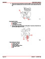
1.
2.
Start engine and warm it up to normal operating temperature.
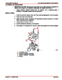
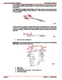
Connect the positive (+) lead from the DVOM to the PUR/WHT timing terminal that
comes from the engine harness.
3.
4.
Connect the negative (–) lead from the DVOM to a good engine ground (–).
With the engine running, there should be 8-10 volts on this circuit. If voltage is not pres-
ent, ensure that there is 12 volts to the Knock Module (PUR wire Terminal “B”).
5.
6.
7.
8.
9.
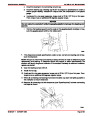
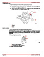
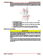
Advance the throttle to approximately 1500 rpm.
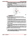
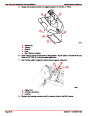
Disconnect the harness connector (BLU wire) from the Knock Sensor.
Connect the unpowered test light to a positive (+) 12 volt source.
To simulate an AC voltage, rapidly tap the Knock Sensor harness terminal with test light.
If Knock Module and wiring is functioning properly, you should see a voltage drop on the
DVOM. If a voltage drop is not seen, check the BLU wire from the sensor to the Knock
Module for a short or open circuit. If the circuit is functioning properly to this point, the
Knock Sensor may not be functioning.
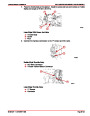
10.
11.
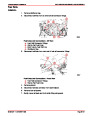
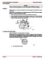
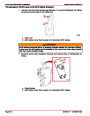
Reconnect the Knock Sensor harness connector to the sensor.
While still watching the DVOM, lightly and rapidly tap on the engine block near the Knock
Sensor with a small hammer. If the Knock Sensor is functioning properly, you should see
the voltage decrease. If a voltage drop is not seen, the Knock Sensor is faulty.
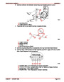
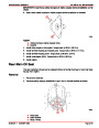
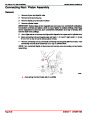
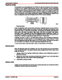
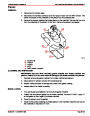
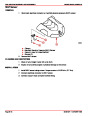
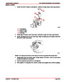
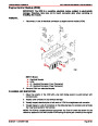
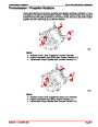
INSTALLATION OF KNOCK SENSOR
IMPORTANT: The correct Knock Module and Sensor must be used. Using an incor-
rect Knock Module or sensor will result in unrecognized spark knock and engine
damage.
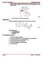
IMPORTANT: It is very important that the Knock Sensor be torqued to the exact speci-
fication. Incorrect torquing will result in unsatisfactory performance. DO NOT use
sealer on threads.
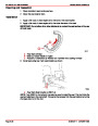
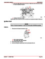
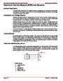
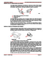
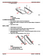
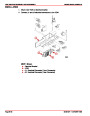
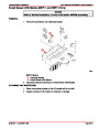
1.
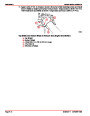
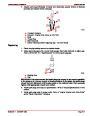
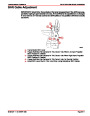
Install Knock Sensor in engine block. Torque to 14 lb-ft (19 Nm).
a
73756
a - Knock Sensor
2.
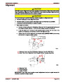
Connect electrical connector to Knock Sensor.
Page 4B-16
90-861327--1 OCTOBER 1999
| Categories | Mercury MerCruiser Manuals |
|---|---|
| Tags | Mercury MerCruiser 305 CID, Mercury MerCruiser 350 CID |
| Model Year | 1998, 1999, 2000, 2001 |
| Download File |
|
| Document File Type | |
| Copyright | Attribution Non-commercial |
(1 votes, average: 4 out of 4)
Marine readers have rated Mercury MerCruiser Engines Service Manual Number 24 GM V-8 305 CID 350 CID 4.0 out of 4.0 based on 1 product reviews. Great performance engine.
Class 1