


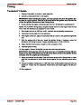


SERVICE MANUAL NUMBER 24
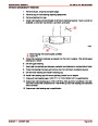
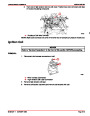
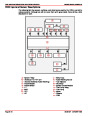
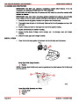
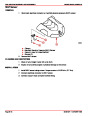
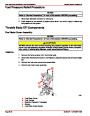
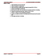
WIRING DIAGRAMS
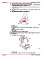
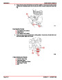
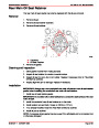
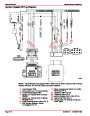
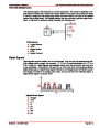
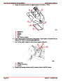
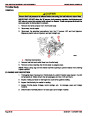
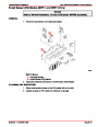
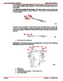
MEFI 3 5.0L EFI and 5.7L EFI Engines
NOTE: All BLACK wires with a ground symbol are interconnected within the EFI system har-
ness.
1
2
3
4
5
6
7
8
9
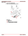
- Fuel Pump
- Throttle Body
- Distributor
- Coil
- Manifold Air Temperature (MAT) Sensor
- Data Link Connector (DLC)
- Manifold Absolute Pressure (MAP) Sensor
- Knock Sensor
12- Electronic Control Module (ECM)
13- Water Temperature Sender
14- Fuel Pump Relay
15- Ignition/System Relay
16- Fuses (15 Amp) Fuel Pump, (15 Amp) ECM/DLC/Battery,
(10 Amp) ECM/Injector/Ignition/Knock Module
17- Oil Pressure Sensor
18- Harness Connector To Starting/Charging Harness
19- Positive (+) Power Wire To Engine Circuit Breaker
20- Shift Plate
- Idle Air Control (IAC)
Throttle Position (TP) Sensor
Engine Coolant Temperature (ECT) Sensor
10-
11-
21- Gear Lube Monitor
22-
Fuel Pressure Switch
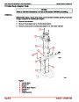
NOTE: Component position and orientation shown is arranged for visual clarity and ease
of circuit identification.
22
21
17
7
5
9
12
10
20
6
2
13
8
11
16
15
18
14
19
1
(–)
(+)
4
3
76063
Index
90-861327--1
OCTOBER 1999
Page 4E-15
| Categories | Mercury MerCruiser Manuals |
|---|---|
| Tags | Mercury MerCruiser 305 CID, Mercury MerCruiser 350 CID |
| Model Year | 1998, 1999, 2000, 2001 |
| Download File |
|
| Document File Type | |
| Copyright | Attribution Non-commercial |
(1 votes, average: 4 out of 4)
Marine readers have rated Mercury MerCruiser Engines Service Manual Number 24 GM V-8 305 CID 350 CID 4.0 out of 4.0 based on 1 product reviews. Great performance engine.
Class 1