


MCM MODELS
SERVICE MANUAL NUMBER 24
8.
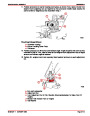
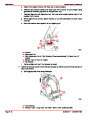
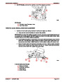
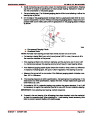
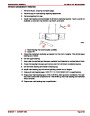
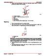
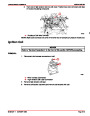
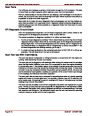
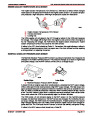
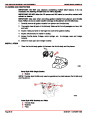
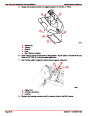
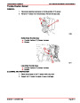
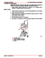
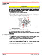
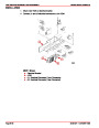
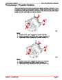
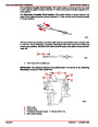
Relieve hoist tension from engine, then slide engine fore or aft as needed to obtain 1/4
in. (6 mm) between flange shoulder and extension shaft housing bearing, as shown.
c
c
b
a
72591
a- Flange Shoulder
b- Bearing
c- 1/4 in. (6 mm)
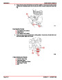
9.
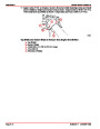
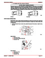
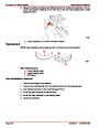
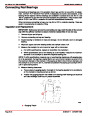
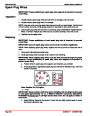
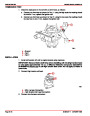
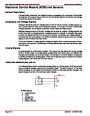
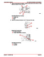
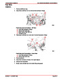
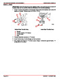
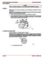
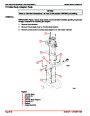
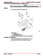
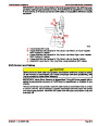
Position engine for correct engine and drive shaft lateral alignment as follows:
a. Measure the length of “a” and “b” to the centers of bolt holes. They MUST BE
EQUAL. If they are not equal, slide the aft and forward ends of the engine equal
amounts in opposite directions to obtain equal lengths for “a” and “b.”
a
b
70246
Top View Shown
These Dimensions Must Be Equal
a- Must equal (b)
b- Must equal (a)
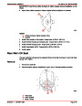
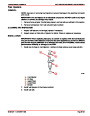
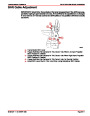
b. Recheck Step 8. If Step 8 is not as specified, adjust and recheck Step 9a. Continue
this process until both Steps 8 and 9a are as specified.
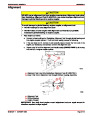
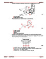
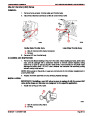
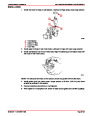
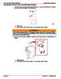
10.
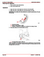
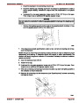
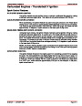
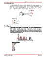
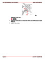
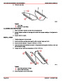
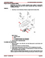
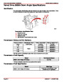
After engine has been aligned correctly, fasten front and rear engine mounts to stringers.
Tighten securely.
a
a
72536
Typical Mounting Shown
a- Mounting Bolts
Index
Page 2A-12
90-861327--1 OCTOBER 1999
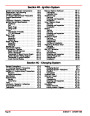
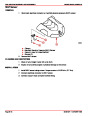
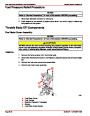
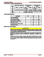
| Categories | Mercury MerCruiser Manuals |
|---|---|
| Tags | Mercury MerCruiser 305 CID, Mercury MerCruiser 350 CID |
| Model Year | 1998, 1999, 2000, 2001 |
| Download File |
|
| Document File Type | |
| Copyright | Attribution Non-commercial |
(1 votes, average: 4 out of 4)
Marine readers have rated Mercury MerCruiser Engines Service Manual Number 24 GM V-8 305 CID 350 CID 4.0 out of 4.0 based on 1 product reviews. Great performance engine.
Class 1