


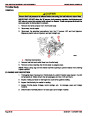


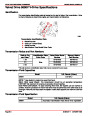


5.0l
/ 305 cid / 5.7l / 350 cid ENGINES
SERVICE MANUAL NUMBER 24
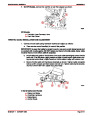
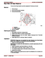
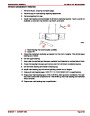
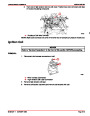
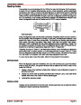
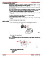
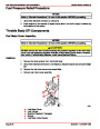
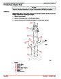
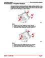
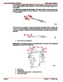
Some of the oil, after leaving the oil cooler and/or filter, is routed to the No. 5 crankshaft main
bearing. The remainder of the oil is routed to the main oil gallery, which is located directly
above the camshaft and runs the entire length of the block. From the main oil gallery, the
oil is routed through individual oil passages to an annular groove in each camshaft bearing
bore. Some of the oil is then used to lubricate camshaft bearings. The remainder of the oil
is routed to the valve lifter oil galleries and No. 1, 2, 3, and 4 crankshaft main bearings by
means of individual oil passages which intersect with the annular grooves.
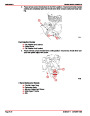
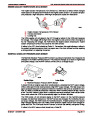
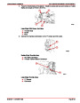
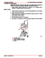
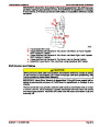
The camshaft bearings have holes which align with the oil passages or annular grooves in
the block and allow oil to flow between the bearings and the camshaft journals. The oil that
is forced out the front end of the No. 1 camshaft bearing drains down onto the camshaft drive
and keeps it lubricated.
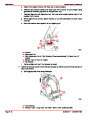
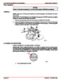
The oil that reaches the crankshaft main bearings is forced through a hole in the upper half
of each bearing and flows between the bearings and the crankshaft journals. Some of the
oil is then routed to the connecting rod bearings through grooves in the upper half of the
crankshaft main bearings and oil passages in the crankshaft. Oil that is forced out the ends
of the connecting rod bearings and crankshaft main bearings and splashes onto the cam-
shaft, cylinder walls, pistons and piston pins, keeping them lubricated. Oil is forced out the
front end of the No. 1 crankshaft main bearing to assist in lubricating the camshaft drive. A
baffle plate, mounted on the bottom of the main bearings or in the oil pan, prevents oil thrown
from the crankshaft and connecting rods from aerating the oil in the oil pan.
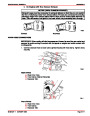
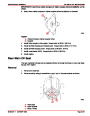
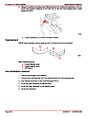
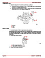
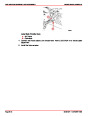
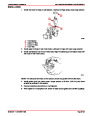
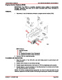
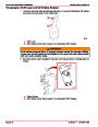
Oil that reaches the valve lifter oil galleries is forced into each hydraulic valve lifter through
holes in the side of the lifter. From here, the oil is forced through the metering valve in each
of the lifters (which controls the volume of oil flow) and then up through the push rods to the
rocker arms. A hole in each rocker arm push rod seat allows the oil to pass through the
rocker arm and lubricate the valve train bearing surfaces. After lubricating the valve train,
oil drains back to the oil pan through oil return holes in the cylinder head and block.
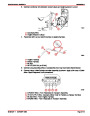
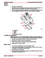
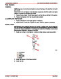
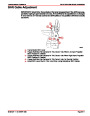
The distributor shaft and gear is lubricated by the oil flowing through the right valve lifter oil
gallery. The fuel pump push rod is lubricated by oil thrown off from the camshaft eccentric.
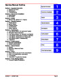
Index
Page 3A-14
90-861327--1 OCTOBER 1999
| Categories | Mercury MerCruiser Manuals |
|---|---|
| Tags | Mercury MerCruiser 305 CID, Mercury MerCruiser 350 CID |
| Model Year | 1998, 1999, 2000, 2001 |
| Download File |
|
| Document File Type | |
| Copyright | Attribution Non-commercial |
(1 votes, average: 4 out of 4)
Marine readers have rated Mercury MerCruiser Engines Service Manual Number 24 GM V-8 305 CID 350 CID 4.0 out of 4.0 based on 1 product reviews. Great performance engine.
Class 1