


SERVICE MANUAL NUMBER 24
MCM MODELS
NOTE: For ease of installation we recommend the use of a chain leveler in the following
steps.
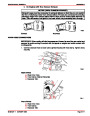
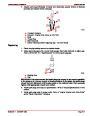
3.
4.
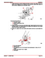
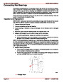
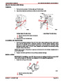
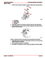
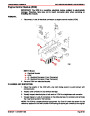
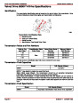
Adjust engine mounts so that an equal amount of up and down adjustment exists.
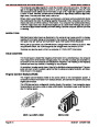
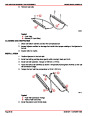
Attach a suitable lifting chain to lifting eyes on engine and adjust so that engine will be
level when suspended, then place engine into its approximate position (in boat) using
an overhead hoist.
5.
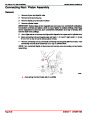
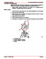
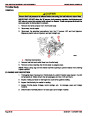
Refer to SECTION 8D - “Drive Shaft Models / Propeller Shaft,” and install drive shaft
while observing precautions in SECTION 8D, especially about aligning gimbal bearing
U-joint centerlines with extension drive shaft U-joint centerlines at bearing support input
shaft. DO NOT install shields at this time.
CAUTION
Engine MUST BE aligned correctly to achieve proper engine operation and to pre-
vent damage to drive shaft. If drive shaft is run at an incorrect angle, damage to uni-
versal joint bearings may result.
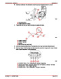
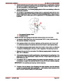
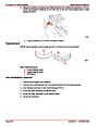
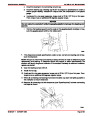
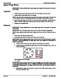
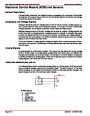
6.
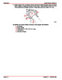
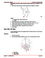
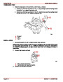
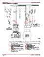
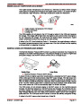
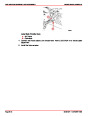
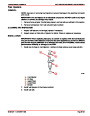
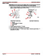
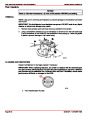
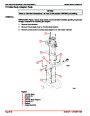
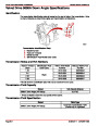
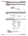
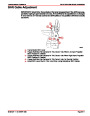
Position base of protractor on drive shaft, then raise or lower engine (as boat construc-
tion permits) until indicator needle is 1° degree to 3° on either side of reading taken in
Step 1. Record this reading in the following chart for later use.
b
c
a
70238
a- Drive Shaft
b- Protractor
c- Output Shaft Flange
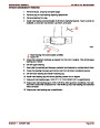
Reading from Step 6.
mark.
degrees to the
side of reference
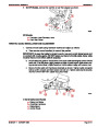
7.
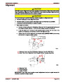
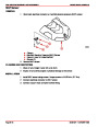
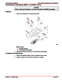
Adjust stringer height so that the stringers just contact the engine mount bases.
CAUTION
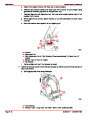
Failure to properly position output shaft flange (as described following) may result
in bearing damage.
Index
90-861327--1
OCTOBER 1999
Page 2A-11
| Categories | Mercury MerCruiser Manuals |
|---|---|
| Tags | Mercury MerCruiser 305 CID, Mercury MerCruiser 350 CID |
| Model Year | 1998, 1999, 2000, 2001 |
| Download File |
|
| Document File Type | |
| Copyright | Attribution Non-commercial |
(1 votes, average: 4 out of 4)
Marine readers have rated Mercury MerCruiser Engines Service Manual Number 24 GM V-8 305 CID 350 CID 4.0 out of 4.0 based on 1 product reviews. Great performance engine.
Class 1