


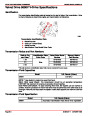


SERVICE MANUAL NUMBER 24
FUEL INJECTION DESCRIPTIONS AND SYSTEM OPERATION
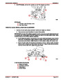
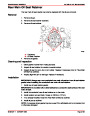
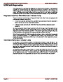
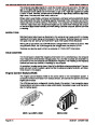
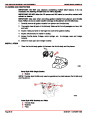
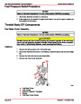
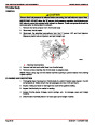
ECM FUNCTION
The ECM supplies 5 or 12 volts to power various sensors or switches. This is done through
resistances in the ECM which are so high in value that a test light will not light when con-
nected to the circuit. In some cases, even an ordinary shop voltmeter will not give an accu-
rate reading because its resistance is too low. Therefore, the use of a 10 megohm input
impedance digital voltmeter is required to assure accurate voltage readings.
MEMORY
There are three types of memory storage within the ECM: ROM, RAM and EEPROM.
Read Only Memory (ROM) is a permanent memory that is physically soldered to the circuit
boards within the ECM. The ROM contains the overall control programs. Once the ROM is
programmed, it cannot be changed. The ROM memory is non-erasable, and does not need
power to be retained.
Random Access Memory (RAM) is the microprocessor “scratch pad.” The processor can
write into, or read from, this memory as needed. This memory is erasable and needs a
constant supply of voltage to be retained.
Electronic Erasable Programmable Read Only Memory (EEPROM) is the portion of the
ECM that contains the different engine calibration information that is specific to each marine
application.
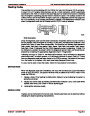
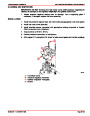
Speed Density System
The Electronic Fuel Injection system is a speed and air density system. The system is based
on speed / density fuel management.
Three specific data sensors provide the ECM with the basic information for the fuel manage-
ment portion of its operation. That is, three specific signals to the ECM establish the engine
speed and air density factors.
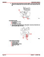
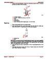
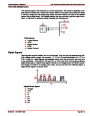
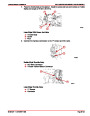
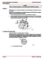
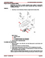
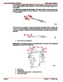
SPEED
The engine speed signal comes from the distributor’s High Energy Ignition (HEI) module to
the ECM on the distributor reference high circuit. The ECM uses this information to deter-
mine the speed or rpm factor for fuel and ignition management.
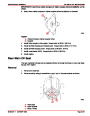
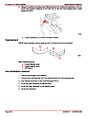
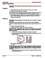
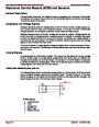
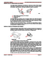
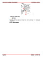
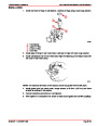
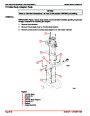
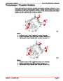
DENSITY
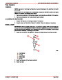
The Manifold Absolute Pressure (MAP) sensor is a 3-wire sensor that monitors the changes
in intake manifold pressure which results from changes in engine loads. These pressure
changes are supplied to the ECM in the form of electrical signals.
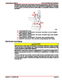
As intake manifold pressure increases (vacuum decreases), the air density in the intake
manifold also increases, and additional fuel is required.
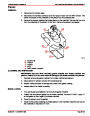
The MAP sensor sends this pressure information to the ECM, and the ECM increases the
amount of fuel injected by increasing the injector pulse width. As manifold pressure
decreases (vacuum increases), the amount of fuel is decreased.
These two inputs from MAP and rpm are the major determinants of the air/fuel mixture, deliv-
ered by the fuel injection system.
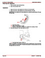
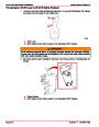
The remaining sensors and switches provide electrical inputs to the ECM which are used
for modification of the air/fuel mixture, as well as for other ECM control functions, such as
Idle Air Control (IAC).
Index
90-861327
OCTOBER 1999
Page 5D-15
| Categories | Mercury MerCruiser Manuals |
|---|---|
| Tags | Mercury MerCruiser 305 CID, Mercury MerCruiser 350 CID |
| Model Year | 1998, 1999, 2000, 2001 |
| Download File |
|
| Document File Type | |
| Copyright | Attribution Non-commercial |
(1 votes, average: 4 out of 4)
Marine readers have rated Mercury MerCruiser Engines Service Manual Number 24 GM V-8 305 CID 350 CID 4.0 out of 4.0 based on 1 product reviews. Great performance engine.
Class 1