


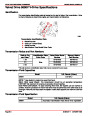


SERVICE MANUAL NUMBER 24
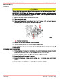
STARTING SYSTEM
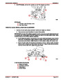
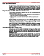
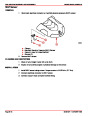
MULTIPLE EFI ENGINE BATTERY PRECAUTIONS
Situation
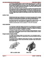
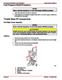
Alternators: Alternators are designed to charge the battery that supplies electrical power
to the engine that the alternator is mounted on. When batteries for two different engines are
connected, one alternator will supply all of the charging current for both batteries. Normally,
the other engine’s alternator will not be required to supply any charging current.
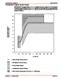
EFI Electronic Control Module (ECM): The ECM requires a stable voltage source. During
multiple engine operation, an onboard electrical device may cause a sudden drain of voltage
at the engine’s battery. The voltage may go below the ECM’s minimum required voltage.
Also, the alternator on the other engine may now start charging. This could cause a voltage
spike in the engine’s electrical system.
In either case, the ECM could shut off. When the voltage returns to the range that the ECM
requires, the ECM will reset itself. The engine will now run normally. This ECM shut down
usually happens so fast that the engine just appears to have an ignition miss.
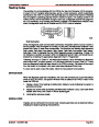
Recommendations
Batteries: Boats with multi-engine EFI power packages require each engine be connected
to its own battery. This ensures that the engine’s Electronic Control Module (ECM) has a
stable voltage source.
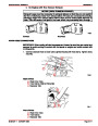
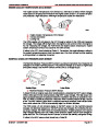
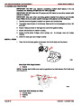
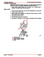
Battery Switches: Battery switches should always be positioned so each engine is running
off its own battery. DO NOT operate engines with switches in BOTH or ALL position. In an
emergency, another engine’s battery can be used to start an engine with a dead battery.
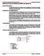
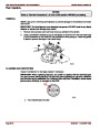
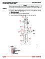
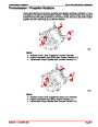
Battery Isolators: Isolators can be used to charge an auxiliary battery used for powering
accessories in the boat. They should not be used to charge the battery of another engine
in the boat unless the type of isolator is specifically designed for this purpose.
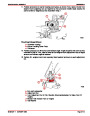
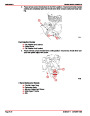
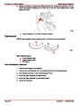
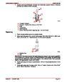
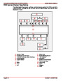
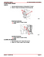
NOTE: Sure Power Industries Inc., Model 32023A meets this design specification.
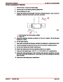
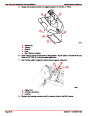
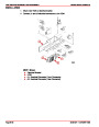
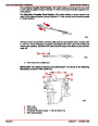
1.
2.
3.
4.
5.
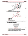
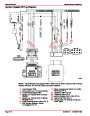
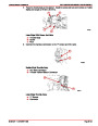
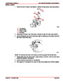
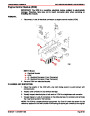
The boat may have 2 engines connected to a single Model 32023A battery isolator.
The Model 32023A battery isolator is connected to 2 banks of batteries.
Each bank contains 2 batteries with the cranking battery for 1 engine in each bank.
The second battery in each bank is connected in parallel to the cranking battery.
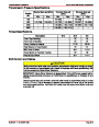
The Model 32023A battery isolator is designed for this type of use; 2 battery banks, 2
charging sources, 120 amps (maximum alternator output).
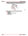
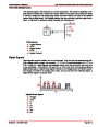
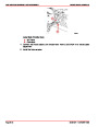
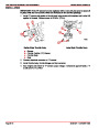
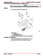
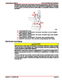
6.
When the engines are running, either engine’s alternator could be charging either bank
of batteries through the Model 32023A battery isolator.
Any other manufacturer’s battery isolator that is the same type as the Sure Power Inc.,
Model 32023A could also be used.
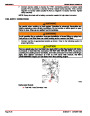
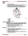
Generators: The generator’s battery should be considered another engine’s battery.
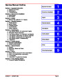
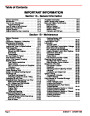
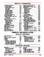
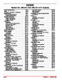
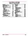
Index
90-861327--1
OCTOBER 1999
Page 4A-5
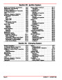
| Categories | Mercury MerCruiser Manuals |
|---|---|
| Tags | Mercury MerCruiser 305 CID, Mercury MerCruiser 350 CID |
| Model Year | 1998, 1999, 2000, 2001 |
| Download File |
|
| Document File Type | |
| Copyright | Attribution Non-commercial |
(1 votes, average: 4 out of 4)
Marine readers have rated Mercury MerCruiser Engines Service Manual Number 24 GM V-8 305 CID 350 CID 4.0 out of 4.0 based on 1 product reviews. Great performance engine.
Class 1