


SERVICE MANUAL NUMBER 24
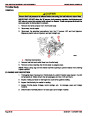
STARTING SYSTEM
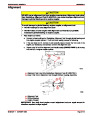
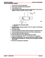
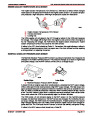
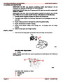
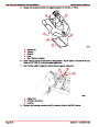
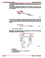
6.
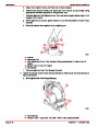
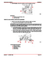
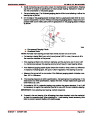
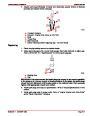
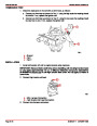
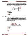
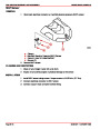
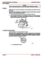
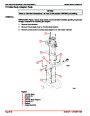
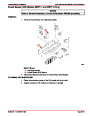
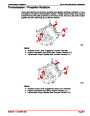
If clearance is not within limits of .010-.160 in. (0.25-4.00 mm), it may indicate excessive
wear of solenoid linkage, shift lever yoke, or improper assembly of shift lever mecha-
nism. Replace solenoid switch, since no provision is made for adjusting pinion clear-
ance.
a
b
c
72077
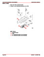
a- Pinion
b- Retainer
c- Feeler Gauge
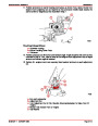
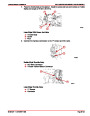
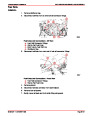
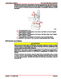
Installation
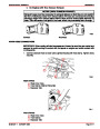
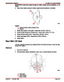
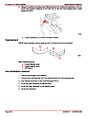
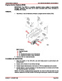
IMPORTANT: Install special mounting shim (if equipped) between starter motor and
engine block.
1.
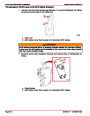
2.
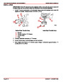
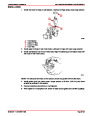
Place starter motor in position and install mounting bolts. Torque bolts to 30 lb-ft (41 Nm).
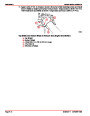
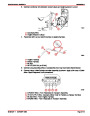
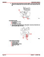
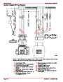
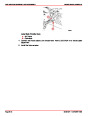
Connect YELLOW/RED wire to terminal S of solenoid. Connect ORANGE wire, RED
wire, and battery cable to large terminal of solenoid. Tighten fasteners securely. Coat
terminals with Quicksilver Liquid Neoprene. Install battery cable boot, if so equipped.
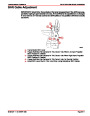
3.
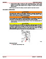
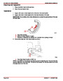
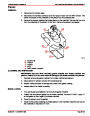
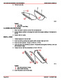
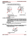
Connect battery cables to battery in the following order. Connect positive (+) cable to
positive (+) battery terminal and tighten cable clamp. Then connect negative (–) cable
to negative (–) terminal and tighten clamp.
Index
90-861327--1
OCTOBER 1999
Page 4A-29
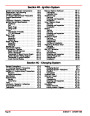
| Categories | Mercury MerCruiser Manuals |
|---|---|
| Tags | Mercury MerCruiser 305 CID, Mercury MerCruiser 350 CID |
| Model Year | 1998, 1999, 2000, 2001 |
| Download File |
|
| Document File Type | |
| Copyright | Attribution Non-commercial |
(1 votes, average: 4 out of 4)
Marine readers have rated Mercury MerCruiser Engines Service Manual Number 24 GM V-8 305 CID 350 CID 4.0 out of 4.0 based on 1 product reviews. Great performance engine.
Class 1