


SERVICE MANUAL NUMBER 24
MIE MODELS
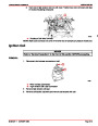
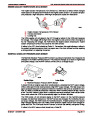
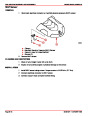
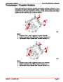
4.
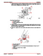
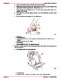
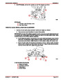
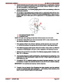
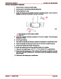
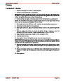
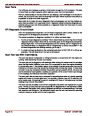
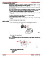
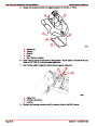
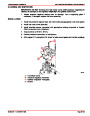
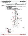
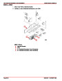
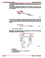
Remove top transmission mounting bolt and lockwasher from left (valve) side of trans-
mission; position bracket, replace bolt and lockwasher.
b
a
22457
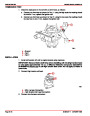
a- Bolt
b- Lock Washer
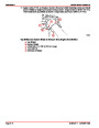
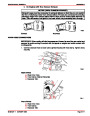
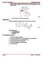
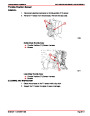
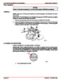
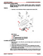
5.
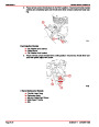
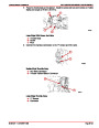
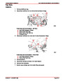
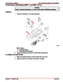
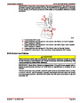
Fasten pivot pin securely through hole (not countersunk) in adaptor plate using lock-
washer and nut.
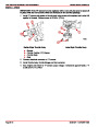
6.
7.
Attach adaptor plate to transmission shift lever using screw, lockwasher and nut.
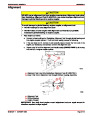
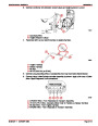
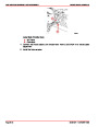
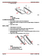
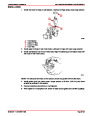
Fasten cable hubs in cable clip and screw terminals onto cable rods until holes in
terminals line up with pivot pin. Hold each terminal securely to prevent from turning and
tighten cable nut against terminal.
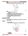
NOTE: Be sure control head hand lever and transmission shift lever are in neutral position
during the above installation.
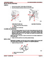
8.
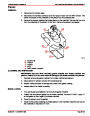
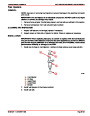
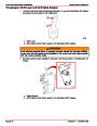
Place terminals on pivot pin and secure with E-ring.
NOTE: When using this kit with Models “S” or “SR” controls, adjust the stop screws in the
control head to prevent cable from jamming the clutch arm against its stops at forward and
reverse.
9.
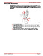
Refer to control head installation instructions for final check and adjustment procedures.
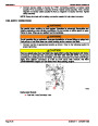
10.
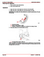
Connect battery cables to battery by FIRST connecting positive (+) battery cable end
to positive (+) battery terminal. Tighten clamp securely. Then, connect negative (–) bat-
tery cable end to negative (–) battery terminal. Tighten clamp securely.
90-861327--1
OCTOBER 1999
Page 2B-23
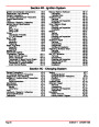
| Categories | Mercury MerCruiser Manuals |
|---|---|
| Tags | Mercury MerCruiser 305 CID, Mercury MerCruiser 350 CID |
| Model Year | 1998, 1999, 2000, 2001 |
| Download File |
|
| Document File Type | |
| Copyright | Attribution Non-commercial |
(1 votes, average: 4 out of 4)
Marine readers have rated Mercury MerCruiser Engines Service Manual Number 24 GM V-8 305 CID 350 CID 4.0 out of 4.0 based on 1 product reviews. Great performance engine.
Class 1