


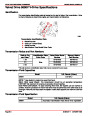


SERVICE MANUAL NUMBER 24
5.0l / 305 cid / 5.7l / 350 cid ENGINES
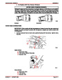
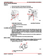
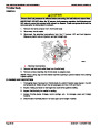
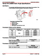
CAUTION
Avoid rapid and severe camshaft and fuel pump push rod wear that could result in
engine damage. Always use the fuel pump push rod specified for use with the cast
iron or steel camshaft in your engine.
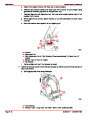
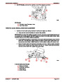
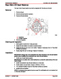
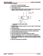
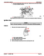
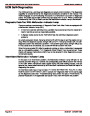
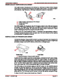
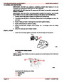
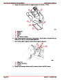
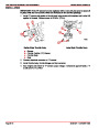
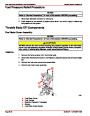
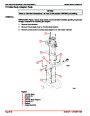
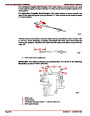
Engines with cast iron camshaft and flat faced lifters, have a taper on the lobes and a spheri-
cal foot on the hydraulic valve lifters. This causes the valve lifters to rotate, thus reducing
wear. Engines with steel camshaft and roller lifters, have eight restrictors held in place by
a retaining plate to keep the hydraulic valve lifters from rotating so that they follow the cam
lobes precisely.
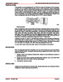
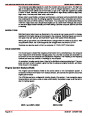
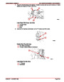
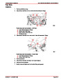
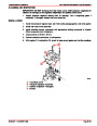
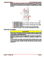
Cylinder Head
The cylinder heads are made of cast iron and have individual intake and exhaust ports for
each cylinder.
Stainless steel or graphite composition head gaskets are used to retard corrosion.
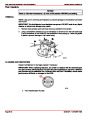
Valve Train
The valves and valve springs are heavy-duty to withstand the high engine speeds
encountered. Valve tips have been hardened to extend valve life. Exhaust valve rotators are
used on some engines to help extend valve life.
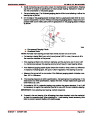
Hydraulic valve lifters ride directly on the camshaft lobes and transmit the thrust of the lobes
to the push rods that actuate the valves through the rocker arm.
In addition to transmitting thrust of the cam lobes, the hydraulic lifters also serve to remove
any clearance (lash) from the valve train to keep all parts in constant contact.
The valve lifters also are used to lubricate the valve train bearing surfaces.
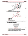
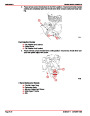
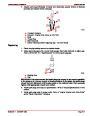
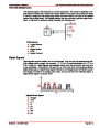
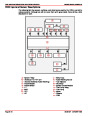
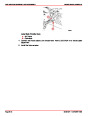
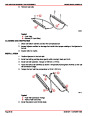
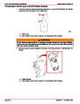
Intake Manifold
The carbureted and throttle body fuel injection manifolds are a double level design for effi-
cient fuel distribution. The upper level of passages feeds cylinders 2, 3, 5 and 8 while the
lower level passages feed cylinders 1, 4, 6 and 7.
The multi-port injection manifold is a tunnel ram design with the injectors mounted directly
above the intake ports in cylinder head.
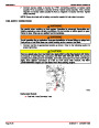
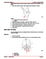
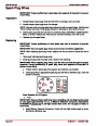
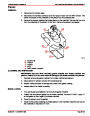
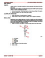
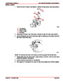
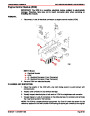
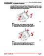
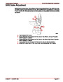
Lubrication System
The engine lubrication system is a force-feed type. Oil is supplied under full pressure to the
crankshaft, connecting rods, camshaft bearings and valve lifters, and is supplied under con-
trolled volume to the push rods and rocker arms. All other moving parts are lubricated by
gravity flow or splash.
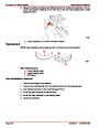
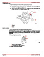
A positive displacement gear-type oil pump is mounted on the rear main bearing cap and
is driven by an extension shaft from the distributor (which is driven by the camshaft). Oil from
the bottom of the pump in the rear of the oil pan is drawn into the oil pump through an oil
pickup screen and pipe assembly.
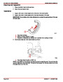
If the screen should become clogged, a relief valve in the screen will open and continue to
allow oil to be drawn into the system. Once the oil reaches the pump, the pump forces the
oil through the lubrication system. A spring-loaded relief valve in the pump limits the maxi-
mum pump output pressure.
After leaving the pump, the pressurized oil flows through a full-flow oil filter. On engines with
an engine oil cooler, the oil also flows through the cooler before returning to the block. A
bypass valve allows oil to bypass the filter and oil cooler should they become restricted.
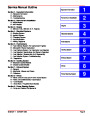
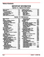
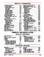
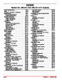
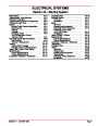
Index
90-861327--1
OCTOBER 1999
Page 3A-13
| Categories | Mercury MerCruiser Manuals |
|---|---|
| Tags | Mercury MerCruiser 305 CID, Mercury MerCruiser 350 CID |
| Model Year | 1998, 1999, 2000, 2001 |
| Download File |
|
| Document File Type | |
| Copyright | Attribution Non-commercial |
(1 votes, average: 4 out of 4)
Marine readers have rated Mercury MerCruiser Engines Service Manual Number 24 GM V-8 305 CID 350 CID 4.0 out of 4.0 based on 1 product reviews. Great performance engine.
Class 1