


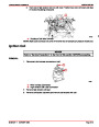


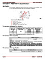


IGNITION SYSTEM
SERVICE MANUAL NUMBER 24
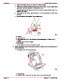
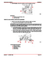
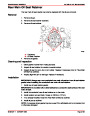
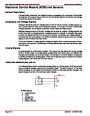
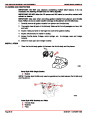
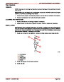
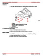
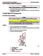
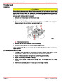
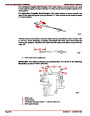
KNOCK RETARD SPARK CONTROL
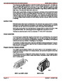
The knock control feature helps provide protection from harmful detonation. Knock control
is handled by the Knock Control Module. This module receives a signal from a sensor that
is mounted on the engine block. The Knock Control Module works in conjunction with the
Ignition Module to retard the timing if spark knock is present.
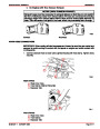
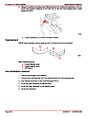
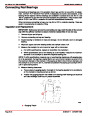
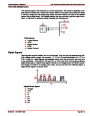
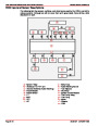
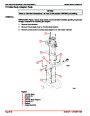
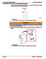
Circuit Description
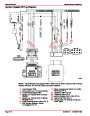
Refer to the circuit wiring diagram on the following page for reference to this circuit descrip-
tion.
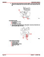
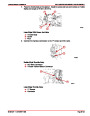
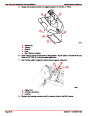
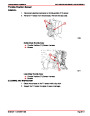
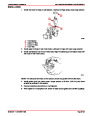
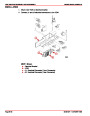
IGNITION CONTROL MODULE
•
The Ignition Module receives its power (+) through the PUR wire “9.”
•
Ignition Module ground (–) is accomplished through the BLK wire “10.”
•
There is also a Case Ground (–) wire “12” that is connected to one of the Ignition
Module attaching screws.
•
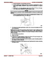
The 12 volt signal from the Ignition Module to the distributor is carried through the
WHT/RED wire “8,” to the distributor sensor and back to the Ignition Module through
the WHT/GRN wire “7.”
•
•
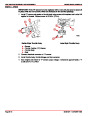
The tachometer signal is carried to the instrument panel through the GRY wire “11.”
The PUR/WHT wire “3” carries the signal from the Knock Control Module to the Igni-
tion Control Module.
•
•
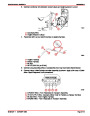
There are two BLK wires “5” that have bullet connectors. This circuit is reserved for
future options. On current models, the two BLK wires must be connected for the sys-
tem to function properly.
The TAN/BLU wire “6” carries a signal from the Audio Warning Circuit to the Ignition
Module.
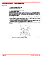
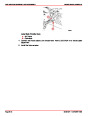
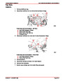
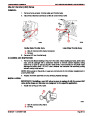
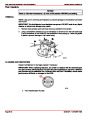
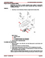
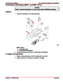
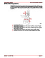
KNOCK CONTROL MODULE
•
•
•
The Knock Control Module receives it’s power (+) from the PUR wire “4.”
Knock Module ground (–) is accomplished through the BLK wire “2.”
The PUR/WHT wire “3” carries the signal from the Knock Control Module to the Igni-
tion Control Module.
•
The BLU wire “1” carries the signal from the Knock Sensor to the Knock Module.
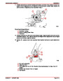
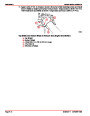
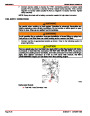
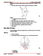
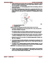
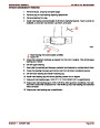
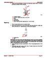
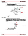
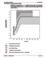
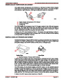
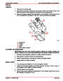
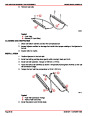
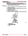
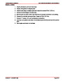
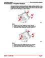
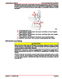
IGNITION CONTROL SYSTEM TIMING LEAD
The ignition control system has a lead with bullet connector “11” that is connected into the
PUR/WHT wire “3.” This lead is used for performing the following tests and procedures:
•
•
•
•
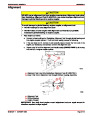
Setting Base Ignition Timing
Setting Engine Idle Speed
Setting Idle Mixture
Testing Knock Control Circuit
This lead, when connected to an engine ground (–), locks the Ignition Control Module into
the Base Timing Mode.
Page 4B-12
90-861327--1 OCTOBER 1999
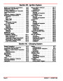
| Categories | Mercury MerCruiser Manuals |
|---|---|
| Tags | Mercury MerCruiser 305 CID, Mercury MerCruiser 350 CID |
| Model Year | 1998, 1999, 2000, 2001 |
| Download File |
|
| Document File Type | |
| Copyright | Attribution Non-commercial |
(1 votes, average: 4 out of 4)
Marine readers have rated Mercury MerCruiser Engines Service Manual Number 24 GM V-8 305 CID 350 CID 4.0 out of 4.0 based on 1 product reviews. Great performance engine.
Class 1