


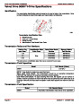


SERVICE MANUAL NUMBER 24
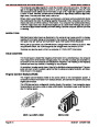
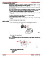
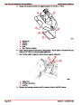
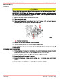
Thunderbolt V Ignition Module
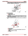
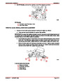
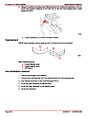
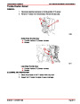
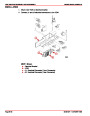
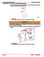
REMOVAL
IGNITION SYSTEM
1.
2.
3.
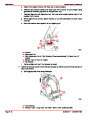
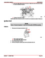
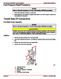
Unplug wiring harness connectors from Ignition Module.
Remove fasteners and hardware retaining Ignition Module to exhaust elbow.
Remove module.
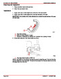
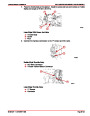
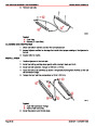
CLEANING AND INSPECTION
1.
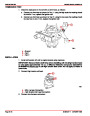
Check that terminals of wiring harness connector are clean and free of corrosion.
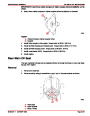
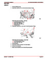
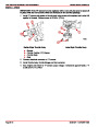
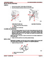
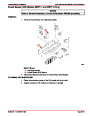
INSTALLATION
1.
2.
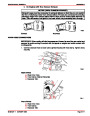
Install Ignition Module using existing hardware. Tighten securely.
Plug connectors into Ignition Module.
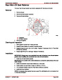
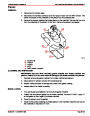
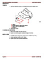
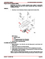
Knock Control Module
DESCRIPTION
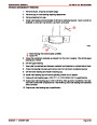
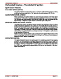
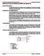
The Knock Control Module monitors the Knock Sensor’s AC voltage signal and supplies an
volt signal, if no spark knock is present, to the Ignition Control Module. If spark knock
8-10
is present, the Knock Control Module will remove the 8-10 volt signal to the Ignition Control
Module.
a
b
c
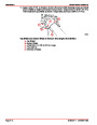
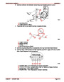
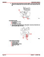
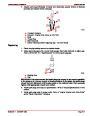
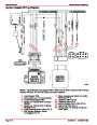
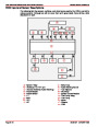
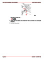
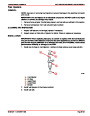
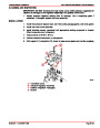
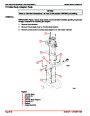
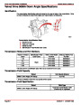
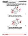
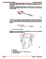
Knock Sensor System
a - Positive Lead (12 Volts)
b - 8-10 Volts To Knock Sensor
c - Knock Sensor
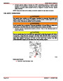
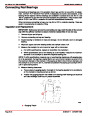
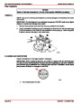
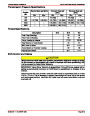
IMPORTANT: The correct Knock Module and Sensor must be used. Using an incor-
rect Knock Module or Sensor will result in unrecognized spark knock and engine
damage.
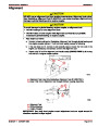
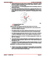
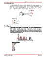
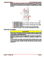
The Knock Module terminal B is powered by 12 volts from the ignition switch. If the 12 volt
power source is not present, the Knock Module cannot send an 8-10 volt signal to the Igni-
tion Control Module and a false constant spark retard will result.
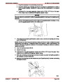
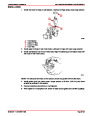
Terminal “E” of the Knock Module is the signal line from the Knock Sensor. If this circuit
opens or shorts to ground, the Knock Module will never remove the 8-10 volt signal from
terminal “C” and no spark retard will occur.
The ground circuit for the Knock Module is connected to terminal “D.” If the ground circuit
opens, the Knock Module will not be able to remove the 8-10 volt signal and spark knock
cannot be controlled.
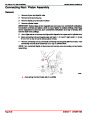
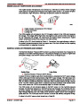
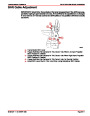
IMPORTANT: If Knock Sensor wire is routed too close to secondary ignition wires, the
Knock Module may see the interference as a knock signal, resulting in false timing
retard.
IMPORTANT: If there is abnormal mechanical engine noise (rattles or knocks), they
may give a false knock retard signal. If fuel octane is too high or too low, a false signal
can also be sent.
90-861327--1
OCTOBER 1999
Page 4B-15
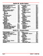
| Categories | Mercury MerCruiser Manuals |
|---|---|
| Tags | Mercury MerCruiser 305 CID, Mercury MerCruiser 350 CID |
| Model Year | 1998, 1999, 2000, 2001 |
| Download File |
|
| Document File Type | |
| Copyright | Attribution Non-commercial |
(1 votes, average: 4 out of 4)
Marine readers have rated Mercury MerCruiser Engines Service Manual Number 24 GM V-8 305 CID 350 CID 4.0 out of 4.0 based on 1 product reviews. Great performance engine.
Class 1