


MULTI-PORT FUEL INJECTION DESCRIPTIONS AND SYSTEM OPERATION
SERVICE MANUAL NUMBER 23
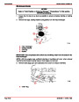
THROTTLE POSITION (TP) SENSOR
The Throttle Position (TP) Sensor is a potentiometer connected to the throttle shaft on the
throttle body. The TP has one end connected to 5 volts from the ECM and the other to ECM
ground. A third wire is connected to the ECM to measure the voltage from the TP. As the
throttle valve angle is changed, the voltage output of the TP also changes. At a closed
throttle position, the voltage output of the TP is low (approximately .5 volt). As the throttle
valve opens, the output increases so that at wide-open-throttle (W.O.T.), the output voltage
should be near 4.5 volts. By monitoring the output voltage from the TP, the ECM can deter-
mine fuel delivery based on throttle valve angle (driver demand). A broken or loose TP can
cause intermittent bursts of fuel from the injector and an unstable idle, because the ECM
thinks the throttle is moving.
73049
If the TP circuit is open or shorted, the ECM will set a Code 21. A problem in any of the TP
circuits will set a Code 21 (Code 22 on 7.4L (L-29) MPI Models only). Once a trouble code
is set, the ECM will use a default value for TP.
DISTRIBUTOR REFERENCE (DIST REF)
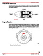
GM refers to this as Ignition Control (IC). The distributor reference (engine speed signal)
is supplied to the ECM by way of the “Dist Ref Hi” line from the High Energy Ignition (HEI).
This pulse counter type input creates the timing signal for the pulsing of the fuel injectors,
as well as the Ignition Control (IC) functions. This signal is used for a number of control and
testing functions within the ECM.
DISCRETE SWITCH INPUTS
Several discrete switch inputs are utilized by the system to identify abnormal conditions that
may affect engine operation. These switches are used in conjunction with the ECM to detect
critical conditions to engine operation.
The switches which are used with the fuel injection system to detect critical engine operation
parameters are:
Switch
Normal State
N/O (With Pressure)
N/O (When Full)
N/O (When Cold)
Oil Pressure
Gear Lube Monitor Level on Sterndrive
Transmission Temperature on MIE Models
Normally Closed
(When In Neutral)
Shift Interrupt / Load Anticipation1
1
Shift Interrupt is not used. Load Anticipation is used only on MIE (inboard) models.
Page 5B-24
90-861326--1 MARCH 1999
| Categories | Mercury MerCruiser Manuals |
|---|---|
| Tags | Mercury MerCruiser 454 CID, Mercury MerCruiser 502 CID |
| Model Year | 1998, 1999, 2000, 2001 |
| Download File |
|
| Document File Type | |
| Copyright | Attribution Non-commercial |
(1 votes, average: 5 out of 5)
Marine readers have rated Mercury MerCruiser GM V8 GM V8 454 CID 7.4L and 502 cid 8.2L Marine Engines Service Manual Number 23 5.0 out of 5.0 based on 1 product reviews. Just need the manual. Wrote review. Can't technically review what I haven't seen yet...