


SERVICE PROCEDURES REQUIRING MINOR DISASSEMBLY
SERVICE MANUAL NUMBER 28
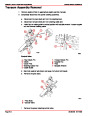
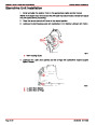
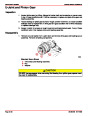
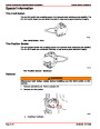
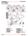
High Performance Transom Assembly - Without Electrical Trim Sender and
Trim Limit Switch
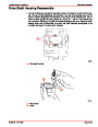
IMPORTANT: The electrical Trim Limit Switch and Trim Position Sender are not
present on this transom assembly. Without a Trim Limit Switch, the sterndrive unit
can be trimmed UP/OUT beyond the position where the sterndrive unit has side
support from the gimbal ring at any throttle setting. It is highly recommended that a
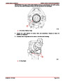
mechanical (cable actuated) Trim Position Indicator be installed to provide important
sterndrive unit trim angle information to the operator and that the Trim Indicator be
marked to clearly indicate the maximum UP/OUT position where side support is still
provided. The sterndrive unit should not be trimmed to a position beyond gimbal ring
side support at engine speeds above 1200 rpm.
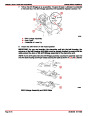
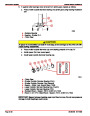
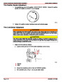
WARNING
Avoid personal injury or damage to sterndrive unit. Do not trim sterndrive unit to
an UP/OUT position where the sterndrive unit receives no side support from the
gimbal ring at engine speeds above 1200 rpm. Refer to a properly marked mechani-
cal Trim Position Indicator.
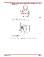
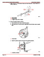
1.
2.
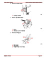
Install WARNING DECAL (Contained in the transom assembly box) at the operator
station in a place where it will be clearly visible to the operator.
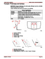
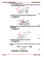
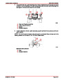
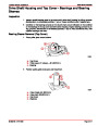
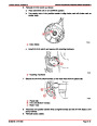
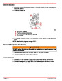
To mark the maximum Trim UP/OUT position on the mechanical trim indicator, proceed
as follows:
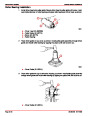
a. Trim sterndrive unit(s) to the FULL DOWN/IN position.
b. Ensure that the mechanical trim indicator indicates FULL DOWN/IN position. Adjust
the indicator following the manufacturers recommendations.
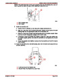
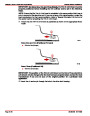
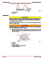
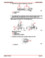
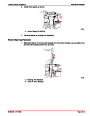
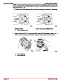
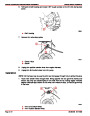
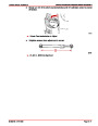
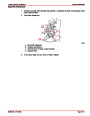
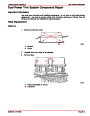
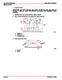
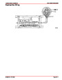
c. Slowly raise the sterndrive unit(s) until the trim limit point is reached. The trim limit
point can be determined by measuring the amount of trim cylinder extension. The
dimension for the Bravo sterndrive units is 21-3/4 in. (552 mm), which is measured
from front anchor point to rear anchor point centerlines as shown following.
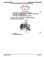
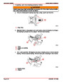
a
50464
a - Trim Limit Dimension 21-3/4 in. (552 mm)
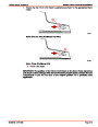
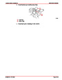
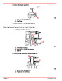
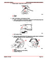
3.
With the trim cylinders at this position, place a mark on the mechanical trim indicator in
console.
a. Raise and lower sterndrive unit(s) several times to ensure that the trim limit point is
properly marked.
INDEX
Page 4A-18
90-863160 MAY 2000
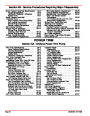
| Categories | Mercury MerCruiser Manuals |
|---|---|
| Tags | MerCruiser Sterndrives 90-863160 |
| Model Year | 1998, 1999, 2000, 2001, 2002, 2003, 2004, 2005, 2006, 2007, 2008, 2009, 2010, 2011 |
| Download File |
|
| Document File Type | |
| Copyright | Attribution Non-commercial |
(1 votes, average: 3 out of 3)
Marine readers have rated Mercury MerCruiser Bravo Outdrives Sterndrives Marine Engines Service Manual Number 28 3.0 out of 3.0 based on 1 product reviews. I could not find any mention of the seawater pump assembly.
Maybe I have the wrong unit