


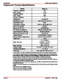


SERVICE MANUAL NUMBER 26
TROUBLESHOOTING
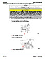
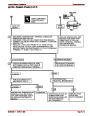
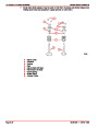
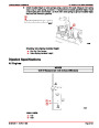
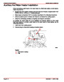
EST Ignition System Check
Test Description
Numbers below refer to circled numbers on the diagnostic chart.
1.
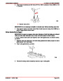
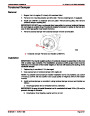
Two wires are checked, to ensure that an open is not present in a spark plug wire.
a. If spark occurs with EST connector disconnected, pick-up coil output is too low for
EST operation.
2.
3.
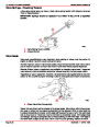
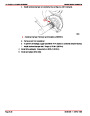
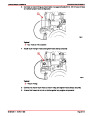
A spark indicates the problem must be the distributor cap or rotor.
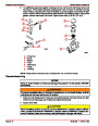
Normally, there should be battery voltage at the “C” and “+” terminals. Low voltage would
indicate an open or a high resistance circuit from the distributor to the coil or ignition
switch. If “C” terminal voltage was low, but “+” terminal voltage is 10 volts or more, circuit
from “C” terminal to ignition coil or ignition coil primary winding is open.
4.
5.
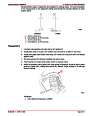
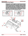
Checks for a shorted module or grounded circuit from the ignition coil to the module. The
distributor module should be turned “OFF,” so normal voltage should be about 12 volts.
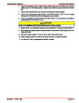
If the module is turned “ON,” the voltage would be low, but above 1 volt. This could cause
the ignition coil to fail from excessive heat. With an open ignition coil primary winding,
a small amount of voltage will leak through the module from the “BAT” to the “TACH”
terminal.
Applying a voltage (1.5 to 8 volts) to module terminal “P” should turn the module “ON”
and the “tach” terminal voltage should drop to about 7-9 volts. This test will determine
whether the module or coil is faulty or if the pick-up coil is not generating the proper
signal to turn the module “ON.” This test can be performed by using a DC battery with
a rating of 1.5 to 8 volts. The use of the test light is mainly to allow the “P” terminal to
be probed more easily. Some digital multi-meters can also be used to trigger the module
by selecting ohms, usually the diode position. In this position the meter may have a
voltage across its terminals which can be used to trigger the module. The voltage in the
ohm’s position can be checked by using a second meter or by checking the
manufacturer’s specification of the tool being used.
6.
This should turn “OFF” the module and cause a spark. If no spark occurs, the fault is
most likely in the ignition coil because most module problems would have been found
before this point in the procedure. A module tester could determine which is at fault.
Index
90-861329--1
MARCH 1999
Page 1C-11
| Categories | Mercury MerCruiser Manuals |
|---|---|
| Tags | Mercury MerCruiser 181 CID |
| Model Year | 1998, 1999, 2000, 2001, 2002, 2003, 2004, 2005, 2006, 2007, 2008, 2009, 2010, 2011 |
| Download File |
|
| Document File Type | |
| Copyright | Attribution Non-commercial |
(6 votes, average: 5 out of 5)
Marine readers have rated Mercury MerCruiser GM 4 Cylinder 181 cid 3.0L Marine Engines Service Manual Number 26 5.0 out of 5.0 based on 6 product reviews. Thanks for sharing this material. Helps a lot after suffering with bad mechanics. spend too much money and nothing very good
great manual, makes impossible jobs possible. without a manual you can not do the job, a must have.
Great resource. Excellent information provided.
Need help to install automate choke
Need help to instal automate choke