


effort is not reduced to a level where it can be
wheeled “lock to lock” without a concen trated turning
effort.
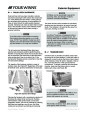
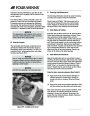
The reading on the gauge can be adjusted by loosen-
ing the three screws securing the electrical sending
unit and turning the sending unit either clockwise and
counterclockwise slightly. The reading will vary
accordingly.
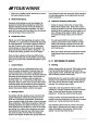
Steering effort can vary significantly with engine
acceleration, steering angle, trim angle, and
sea condition. Be prepared for additional
steering loads at all times.
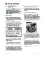
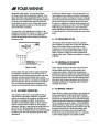
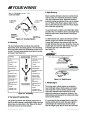
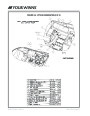
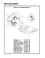
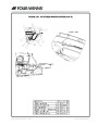
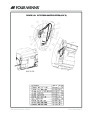
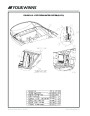
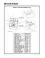
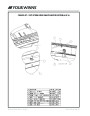
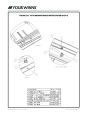
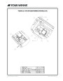
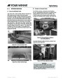
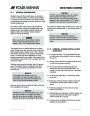
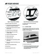
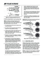
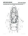
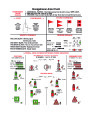
G - 3 RUDDERS - Inboard Models
On inboard models, the dual V-drives have two
rudders. These are coupled together at the tiller arms
by a tie bar. The rudders are toed-in at the front to
provide maximum stability on straight ahead runs and
proper tracking through corners. Rudder alignment is
preset at the Four Winns factory. Further alignment
adjustments should not be necessary unless the
rudder or steering system incurs damage. See
Figures G2, G3, & G4.
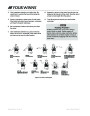
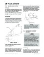
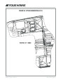
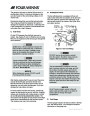
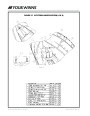
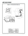
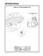
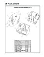
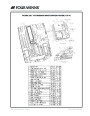
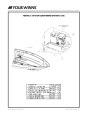
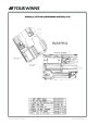
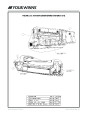
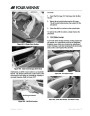
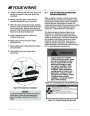
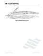
Figure G3: Hydraulic Steering
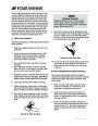
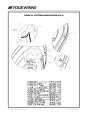
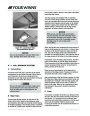
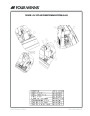
Rudder Alignment Procedures:
G - 5 PROPELLER TORQUE
1.
Dimension A must be 1/2” to 3/4” larger than
dimension B.
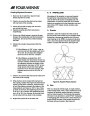
The propeller rotation of a single engine operation will
exert a directional force on the steering sys tem. This
can cause the steering to be harder in one direction
than the other, and is called propeller torque.
2.
Dimension A & B must be measured between the
inside faces and at the bottom of the rudders.
Propeller torque can also cause the boat to wander
(not follow a straight line) when operated at low
speeds. This condition is normal and can be corrected
only by increasing engine rpm. Wind, water currents
and play in steering components can cause equivalent
effects.
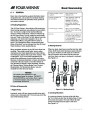
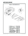
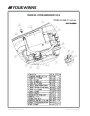
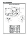
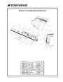
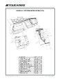
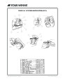
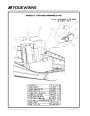
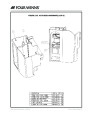
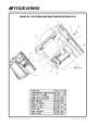
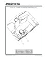
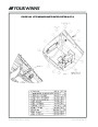
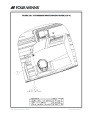
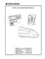
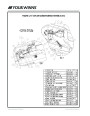
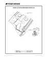
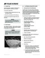
G - 6 STEERING SYSTEM MAINTENANCE
A periodic inspection of all stern drive steering cables,
linkage and helm assemblies should be made. With
inboard models a periodic inspection of the helm
pump and reservoir, hydraulic hoses, the hydraulic
cylinder, tie bar assembly, bearing, seals, rudder
angle sender and rudder should be made. See
Figures G4 - G6. Signs of corrosion, cracking, loosen-
ing of fastenings, excessive wear, or deterioration
should be immediately corrected. Failure to do so
could lead to steering system failure and correspond-
ing loss of control.
Figure G2: Rudder Alignment Specifications
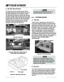
G - 4 RUDDER ANGLE/POSITION
INDICATOR
A rudder angle/position indicator is a device that
indicates the location of the rudders relative to the
straight ahead position. Such a unit is provided on the
inboard V series models and consists of a gauge on
the dash and an electrical sending unit connected to
a rudder tiller arm or the steering assembly.
See Figures G2 & G3.
Steering Systems - Section G
Owner’s Manual Page 71
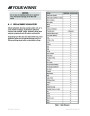
| Categories | Four Winns Manuals, Four Winns V-Series Manuals |
|---|---|
| Tags | Four Winns V375 |
| Model Year | 2011 |
| Download File |
|
| Document Type | Owner's Manual |
| Language | English |
| Product Brand | Boats and Cruisers, Four Winns. For support contact your dealer at http://www.fourwinns.com/locate-dealer.aspx |
| Document File Type | |
| Publisher | fourwinns.com |
| Wikipedia's Page | Outboard Marine Corporation |
| Copyright | Attribution Non-commercial |
(0 votes, average: 0 out of 5)