


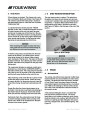


your boat from a distance. This feature when used can
make nighttime boarding much easier and safer.
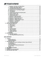
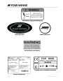
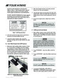
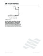
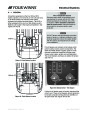
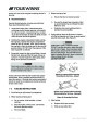
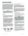
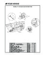
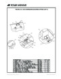
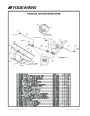
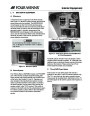
ACC/
Neutra-Salt
(Optional)
ACC/
Wiper
Docking Lts (Opt.)
/Platform Lts
Port/
Trim Tab
Nav/Anc
Lts
ACC/
Windlass
ACC/
(Optional)
Ctsy
Stbd/
Trim Tab
Exhaust
Lts
Eng
Fuel
Gauge
Depth
Sounder
(Optional)
Hatch
Bilge(Optional)
Horn
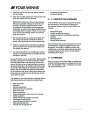
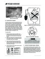
Horn - To sound the horn, press the HORN switch.
Navigation & Anchor Lights - Moving the rotary NAV/
ANC LTS switch towards the NAV position activates
the bow lights, the all-around light and the instrument
lights on the dash. Move the switch to the ANC
position to activate the all-around light. The center
switch posi tion is “OFF”.
Figure H7: Helm Switch Panel
12
12
Volt DC Receptacle - Permits the use of additional
volt equipment such as a cell phone. Using the
appropriate adaptor, the equipment draws power from
the boat’s batteries.
Docking Lights/Platform Lights - The optional docking
lights (if equipped) may be activated by moving the
rotary DOCK/TRANS switch to the DOCK/BOTH
position. To activate the courtesy lights for the swim
platform move the switch to the TRANS position. The
center switch posi tion is “OFF”.
Aft Bilge Pump - The BILGE switch is used to manu-
ally activate the bilge pump in the engine compart-
ment. The bilge pump is used to remove water from
the bilge (bottom of the hull) area of the boat by
pumping that water overboard. The aft bilge pump is
equipped with an automatic bilge switch and will
operate whenever bilge water rises to a level that will
cause the float to move upward.
Trim Tabs - The boat is equipped with electric-
hydraulic trim tabs, the trim tabs are controlled by the
TRIM TAB switches. Refer to Section E-6 - Trim Tabs
for more information.
This automatic bilge pump is active even if the battery
selector switch is in the “OFF” position. The auto matic
bilge pump circuitry is connected directly to the
batteries. When leaving your boat unattended for an
extended period, check the charge on the battery(s)
periodically. Also check the water level in the bilge
and make sure the float switch is functional.
Windlass - The WINDLASS switch activates the
optional windlass. Directional arrows are imprinted on
the helm switch panel above the switch to assist you.
By moving the rotary switch to the “UP” position
(indicated by the upward arrow) raises the anchor.
Moving the switch to the “DOWN” position (indicated
by the downward arrow) lowers the anchor. A circuit
breaker is located on the battery switch panel and
must be in the “ON” position to operate the windlass.
A circuit breaker is also located in the helm circuit
breaker panel to protect the windlass circuitry. Refer to
the Section M-12 in this manual and the manufactur-
er’s literature for additional information.
If the automatic bilge pump must be disabled, discon-
nect the wiring plug near the bilge pump.
Blower - The BLOWER switch is used to activate the
bilge blower. Rotating the switch to the “ON” position,
activates the electric bilge blowers, changing the air in
the engine compartment that may contain gas vapors.
Engine Hatch - The ENG HATCH switch is used to
raise and lower the engine lid by activating two linear
screw jacks. Directional arrows are also imprinted on
the helm switch panel above the switch to assist you.
By moving the rotary switch to the “UP” position
(indicated by the upward arrow) raises the engine lid.
Moving the switch to the “DOWN” position (indicated
by the downward arrow) lowers the engine lid. A circuit
breaker is located on the battery switch panel to
protect the linear screw jacks.
Gasoline vapors can explode resulting in injury
or death. Before starting the engine, check
engine compartment bilge for gasoline or
vapors. Operate blower for four minutes, and
verify blower operation. ALWAYS run the
blower when the vessel is operating below
cruising speed.
Power Seat Option - Activating the optional power
seat switch (installed on the double-wide helm seat
base) allows the driver to move his or her seat forward
or aft to the desired position. The seat will adjust
approximately six (6) inches.
Courtesy (Cockpit) Lights - The CTSY LTS switch is
used to activate the courtesy lights. A key fob remote
control allows you to activate the courtesy lights on
Electrical Systems - Section H
Owner’s Manual Page 70
| Categories | Four Winns H-Series Manuals, Four Winns Manuals |
|---|---|
| Tags | Four Winns H310 |
| Model Year | 2011 |
| Download File |
|
| Document Type | Owner's Manual |
| Language | English |
| Product Brand | Boats and Cruisers, Four Winns. For support contact your dealer at http://www.fourwinns.com/locate-dealer.aspx |
| Document File Type | |
| Publisher | fourwinns.com |
| Wikipedia's Page | Outboard Marine Corporation |
| Copyright | Attribution Non-commercial |
(0 votes, average: 0 out of 5)