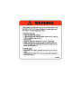


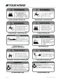


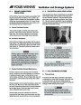


NOTICE
Be sure the two red (positive) cables are
installed on the positive (+) battery
terminals.
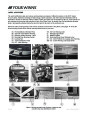
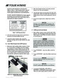
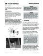
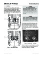
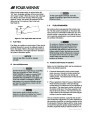
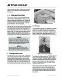
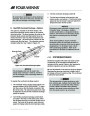
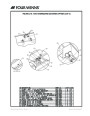
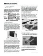
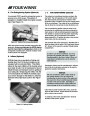
Spring Stay
Helm Breaker
Panel Location
2.
Connect each of the black (negative) battery
cables leading to the engine block to the negative
(-)
battery terminal on each of the two batteries.
When disconnecting the cables from the
battery, make sure all switches are off
and disconnect the black negative
cable(s) first to prevent spark.
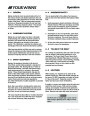
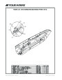
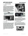
Figure H4: Helm Circuit Breaker Panel Location
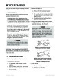
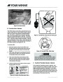
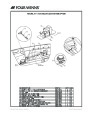
B. Battery Switch Operation - Single
Power to the engine and all 12 volt electrical equip-
ment is controlled at the battery switch panel. Sepa-
rate circuit breakers are provided on the battery
selector switch panel to protect the windlass (if
applicable), engine hatch lift, shower sump, aft bilge
pump, stereo and ship systems. The “SHIP’S SYS-
TEM” circuit breaker must be placed in the “ON”
position to provide power to all non-engine related 12
volt electrical equipment.
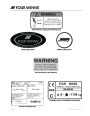
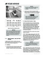
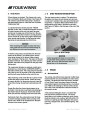
Figure H5: Helm Circuit Breaker Panel
NOTICE
Failure to first bend the spring stay away from
you or in the wrong direction prior to closing
the helm circuit breaker door could result in
damage to the spring stay. If damage does
occur to the spring stay it will need to be
replaced.
A description of the various positions for this battery
switch is as follows:
“OFF” - With the battery selector switch in the “OFF”
position and the “SHIPS SYSTEMS” circuit breaker in
the “OFF” position, all 12 volt power to the boat is shut
off except to the automatic bilge pumps, stereo memo-
ry and windlass (if applicable). Always turn the battery
selector switch and the ship systems breaker switch (if
applicable) to the “OFF” position when the boat is
unattended for an extended period.
H - 2 SINGLE ENGINE - DUAL BATTERY
SYSTEM
A battery selector switch is installed on the dual
battery system. Each, the ships’ systems and engine,
has an individual battery designated to it.
NOTICE
DO NOT turn the battery selector switch to
the “OFF” position while the engine is
running. Alternator and wiring damage
could result.
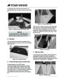
A. Installation
1.
Connect each of the red (positive) battery cables
leading from the battery selector switch to the
positive (+) terminal on each of the two batteries.
“ON” - Turning the switch to position “ON” will use the
engine battery to power the engine and 12 volt engine
related equipment. The ships system battery will not
be used for any engine related equipment, but will
power all other 12 volt equipment on the boat (when
“SHIP SYSTEM” circuit breaker is on). The isolator will
Electrical Systems - Section H
Owner’s Manual Page 67
| Categories | Four Winns H-Series Manuals, Four Winns Manuals |
|---|---|
| Tags | Four Winns H310 |
| Model Year | 2011 |
| Download File |
|
| Document Type | Owner's Manual |
| Language | English |
| Product Brand | Boats and Cruisers, Four Winns. For support contact your dealer at http://www.fourwinns.com/locate-dealer.aspx |
| Document File Type | |
| Publisher | fourwinns.com |
| Wikipedia's Page | Outboard Marine Corporation |
| Copyright | Attribution Non-commercial |
(0 votes, average: 0 out of 5)