


INSTALLATION
Use this procedure to determine whether or not the
boat’s transom height is correct for the engine’s
shaft length:
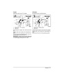
Lift the engine using the lift grips (NOT the tilt grip
or steering handle) and place it in the center of the
boat’s transom.
WARNING
Your engine must not exceed the maximum
horsepower indicated on the boat’s capacity
plate. Such overpowering can cause loss of
control. Contact your DEALER or the boat’s
manufacturer if your boat lacks a capacity
plate.
Boats designed for remote-steered engines
might be overpowered by a tiller-steered
engine of the maximum rated horsepower.
Ask your DEALER or boat manufacturer if
you are unsure about your boat’s suitability.
Incorrectly matched boat and engine tran-
som heights can cause boat instability and
loss of control. Refer to Transom Height
and Shaft Length.
1
1
1.
Lift grips
Prevent lateral movement and possible
engine loss by using the mounting hard-
ware supplied or hardware of sufficient size,
strength, and quality. Refer to Installing the
Engine.
If equipped, tighten clamp screws by hand, NOT
with tools.
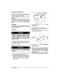
Adjust the motor angle so the antiventilation plate is
parallel with the boat bottom. Refer to Motor Angle
Adjustment.
The resulting position of the antiventilation plate
must be no higher than the boat’s bottom and no
lower than 2 in. (51 mm) below it.
If the resulting position of the antiventilation plate is
above or below the 0 to 2 in. (0 to 51 mm) range,
the engine shaft length must be changed or the
boat’s transom must be modified.
A mounting surface that is damaged or too
thin to support your engine while underway
might fail during operation, causing you to
lose control. Be sure the boat’s transom or
mounting bracket is structurally sound and
between 1 1/2 in. (38 mm) and 2 1/4 in. (57
mm) in thickness.
If you install and operate the engine:
Transom Height and Shaft Length
Lower than recommended — Serious powerhead
damage could result from water entry into the lower
engine cover or overloading from an under-revving
propeller at wide open throttle.
The transom height dimension listed in Engine
Specifications is the height of the boat transom
your engine needs. This dimension is measured at
the transom centerline, perpendicular to the bottom
of the boat.
Higher than recommended — Serious power-
head damage could result from inadequate cooling
or an over-revving propeller. Propeller ventilation
(slippage) often occurs, resulting in poor boat per-
formance.
On a specialty hull, non-planing hull, or on a boat
with a curved transom, these guidelines might not
apply. See your DEALER for special installation in-
formation.
1
3
2
dr3486
1.
2.
3.
Transom height
Antiventilation plate
Final position – 0 to 2 in. (0 to 51 mm)
46
- Maintenance
| Categories | BRP Brand Manuals, Johnson 2-Stroke Manuals, Johnson Brand Manuals, Johnson Outboard Manuals |
|---|---|
| Tags | Johnson 25 hp, Johnson 30 hp, Johnson WPL |
| Model Year | 2004 |
| Download File |
|
| Document File Type | |
| Copyright | Attribution Non-commercial |
(0 votes, average: 0 out of 5)